ARRL 2005 UHF CONTEST AT KMØT
and Rover Mania II
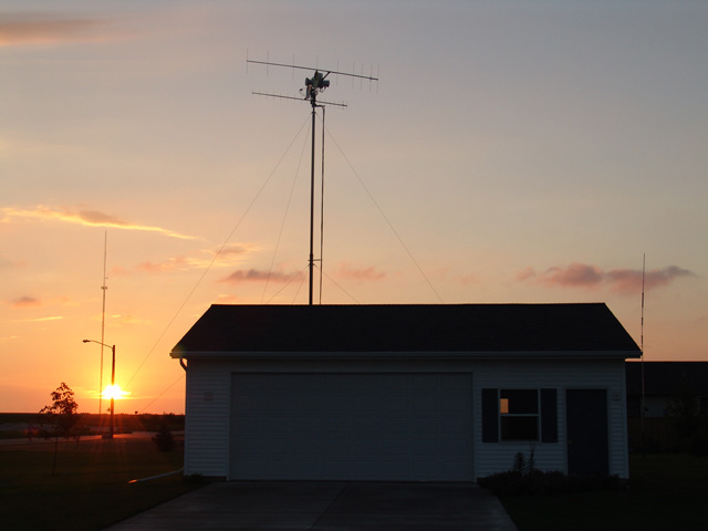
The sun rises on EN13vc....
The year in planning...
"
The NLRS - Northern Lights Radio Society, promoted the "Rover Mania" concept throughout the year, including an open letter to all other VHF+ / Microwave clubs, asking them to promote the "Rover Mania" concept in their area. Hopefully this was well received and helped to generate local activity. We from the NLRS talked amongst ourselves throughout the year about the plans for the upcoming "Rover Mania II" (RMII) and prayed for good propagation along the way!
The KMØT Plan…..
I had lots of things in the hopper for RMII. The first thing was to make sure that I was able to get my spare gear borrowed out. That part would be easy as long as I had some takers. The other part was to look at station improvements; just so I would be able to take advantage of the Rovers should they show up in my area.
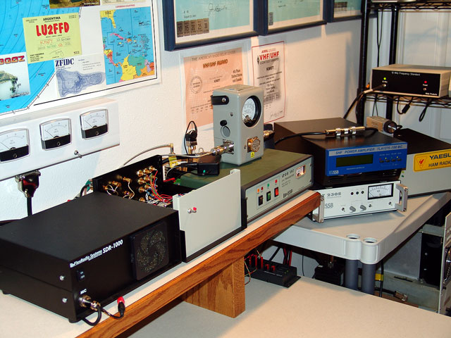
Over the winter, I decided to rip the entire station apart to make room for the SDR-1000 radio. This was a major undertaking and is discussed in the June Contest 2005 write-up. The SDR-1000 implementation was also a major undertaking to use as the microwave IF for 902 MHz and up. See the SDR-1000 part of this website.
The one other major undertaking was redoing the microwave tower, which had the 5.7 and 10 GHz dishes mounted on it. This was to be the meat of the efforts, as the whole project was going to be modeled around how to get things to point more accurately and have the 24 GHz system tower mounted as well.
This was a pretty big bite to chew on and things slowly got going as the snow began to fly over Northwest Iowa.
My 24 GHz dilemma...
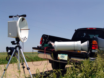
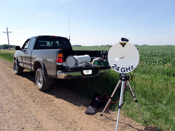
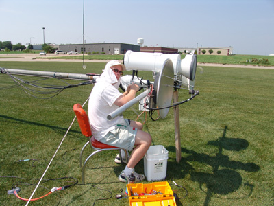
The KMØT Temporary 24 GHz Rover Setup
I sat and looked at the 24 GHz temporary Rover setup. How was I going to box that equipment up and get it on the tower? If I was going to use a dish like I had for the 24 GHz tripod setups, the main thing I was facing was how to waterproof the 24 GHz waveguide splash feed. The end of the wave guide was wide open to the outside world, and the water would travel down that and back into the AST waveguide switch. This I did not think would be a good idea. Even If I could mount the stuff on the tower in a temporary fashion, I figured it would get rained on, thus causing lots of headaches.
So I began to look at a more permanent solution. This led to the conclusion that I needed some kind of new antenna. I spent lots of months since I started out on 24 GHz looking for some type of antenna with a raedome or covered feed. Not many to be found. I had a 2' Andrews dish with a radome, but boy was that thing heavy. Not to mention how hard it would be to point in terms of beam width. And the MA-40 crankup that I was using as the microwave tower had way too much slop in it.
eBay come through again…..
During my search, I came across what was called a Lens Horn antenna. These were being offered by an eBay seller out of the UK. Flann Microwave was the manufacturer and apparently these antennas were brand new, but rated for the 23 GHz band. Research on the Flann Microwave website showed they also had a version for the 24 GHz band, but boy did these antennas look the same!
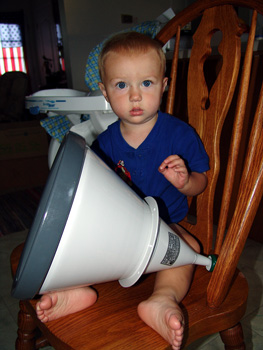
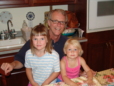
Matthew shown for reference...
It was my guess that if one purchased the Lens Horn antenna directly from Flann Microwave, then the proper nameplate would be put on the antenna. The gain between 23 and 24 GHz would just be a bit different. I also did some basic research on Lens Horn antennas and it seemed that these might be a good solution for what I was looking for, as it seemed the gain per size of aperture was a bit more than a traditional dish.
These were commercial units, meant for point to point communications paths, and rated for outdoor use! The wave guide WR-42 connection at the feed end of the horn looked very inviting. If I could connect that directly to the AST waveguide switch, then I would have virtually no loss whatsoever in the overall system!
So I got on eBay and won two of the units. Did Paypal, which turned out to be very slick as there was an automatic conversion from US Dollars to Pounds. Talk about international commerce! The Lens horn antennas got shipped and arrived in good order.
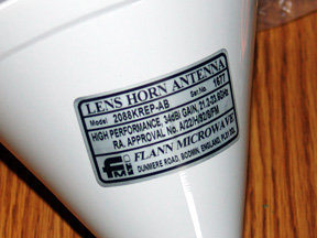
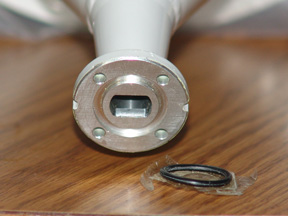
Nameplate info and WR-42 connection...
The model I received is the 250 mm aperture - 2088KREP-AB. It is rated for 21.2 to 23.6 GHz with 34 dBi of mid band gain and about a 3.6 degree H plane 3db beam width. The Flann Microwave site has a PDF one can download on their Lens Horn specs. Noted was the 20880-P antennas, which seemed to match for specifications even though the nameplate on my actual antennas were slightly different. However, their catalog number for the horn rated to 26.5 GHz was the same 20880-P, but the gain was slightly more. This made sense, if the antennas were physically the same, the gain would be a bit more at the higher frequency.
Hmmmm, now what?
I looked over the Lens Horn antenna, boy it was a bit longer than I expected. If I mounted the waveguide switch at the end, then the aluminum Hoffman box I had would not be deep enough. This would be a problem because a box big enough to handle the depth would be much too large in the other dimensions.
I then looked at perhaps putting the waveguide switch off to the side and using some WR-42 waveguide for a hookup to the Lens Horn. This however did not help much as the depth of the antenna to the mounting flange was still too much. This was the main hold up for the 24 GHz tower system, and I spent a few months thinking about it. Numerous iterations of layouts on CAD did not come up with anything suitable. I really wanted that waveguide switch to be mounted directly to the Lens Horn...I did not want to give up any dBs.
MAYDAY MAYDAY - VOSON PLUMBING TO THE RESCUE!
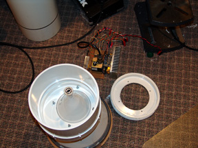
Spring was upon us, it was May 1st and I was running out of time. This must have put the ol noggin into overtime while I slept, as I woke up in a cold sweat thinking of sanitary sewer piping! Wow, what the heck was the wrong with me? But wait....why not do a "linear" approach to the whole problem? Could this be mounted in a large diameter pipe of some sort, that would run the length from the Lens Horn flange and back to cover up the other equipment? This really started the ball rolling!
A bit more head scratching and I gave a call to my cousin Karl at Voson Plumbing in Minnesota. I had worked in plumbing my whole life up until college and my current job. My Dad was a plumber, as was my Grandpa and lots of uncles. So I had been around this stuff for quite some time.
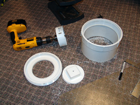
I figured I needed some 8" thin wall PVC and some female adapters with clean-out covers. Karl said "You want what?" I laughed and told him what I was up too....I think he said..."oh..sounds like fun...not." He said he would take a look through the shop and leave the stuff outside for Colleen to pick up over the weekend while she was up running around the cities. Thanks Karl!
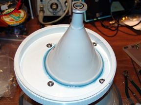
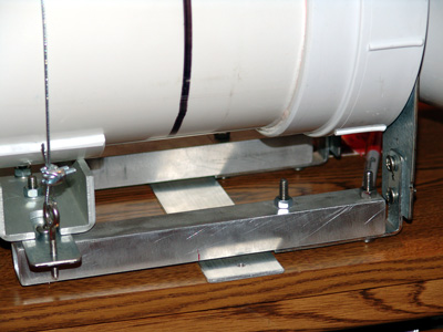
Colleen got back with my pipe and adapters and I started to mock up a preliminary design. This looked like it would work, now to figure out how to mount all the stuff inside the pipe. As I figured out how the clean-out covers would fit on the Lens Horn flange, I made my first cut and got it mounted.
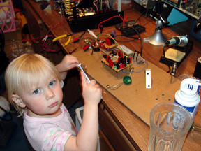
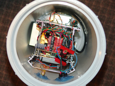
Don't bug me...I'm takin this thingy apart!
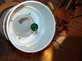
However, the first opening I drilled in the clean-out cover was centered, and when the waveguide switch with power amp and RX preamp was fitted, I realized that the pipe would not slide around it. Good thing I asked for an extra clean-out cover in case I screwed up! So the next one I drilled was offset, and then it appeared the pipe would slide over the main components.
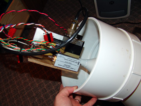
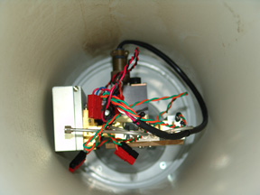
Note the offset hole and how it all now fits!
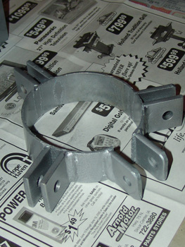
Early trial for mounting straps....
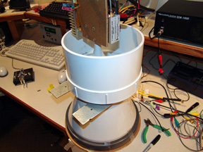
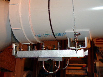
From there, I had to figure how the controller board, mixer, LO and OCXO would mount. It looked like some type of aluminum frame would work, as long as I could somehow get it connected to the Lens Horn flange. This was solved with some 90 degree shelf brackets. Once that was figured out, things started to fall into place and the building began. See my 24 GHz page for details on how the components all go together!
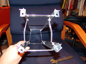
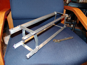
Aluminum square stock made into skeleton frame...
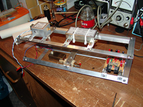
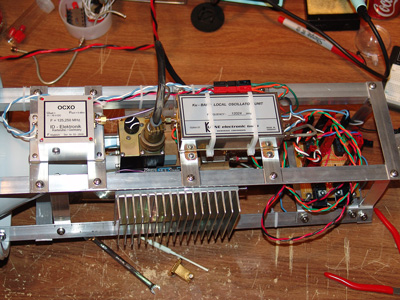
Some basic weatherproofing....initial mounting of OCXO and LO Brick....
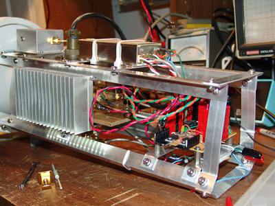
Mounting of components....
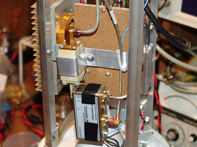
The mixer and image filter mounted on the bottom side...access to pots inside the cover...
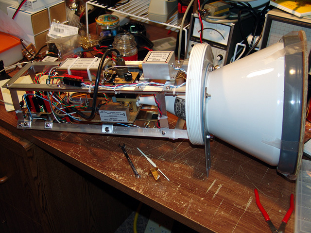
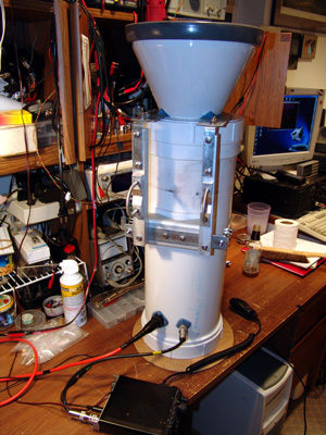
Almost done!
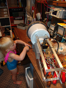
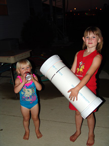
The kids stay involved and show off the outside PVC enclosure....
"I'm on 100"..."no, I am...."
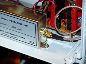
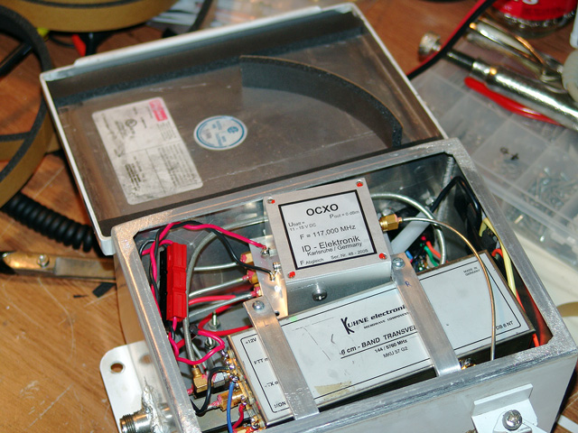
During all this, I began looking into ways to get my 5.7, 10 and 24 GHz systems more stable. After looking at all the GPS locked stuff, PLL multipliers, Rubidium sources, etc. I decided to go with OCXOs from ID-Elektronik in Germany. I first found these on the DB6NT website as advertised as external LO drivers for their transverters. We had been doing fine on 5.7 and 10 GHz, but 24 GHz drifting was a problem for sure. I figured if I was going to do it, might as well figure on fixing all the higher dish band transverters.
The OCXOs (Oven Controlled Crystal Oscillator) came in good order and I began the testing. These were very high quality units as evident from the construction and the specs looked very good. In fact they were ovenized to 80 degrees C, so I figured the high temps inside the dish equipment boxes up on the tower would be ok, as I knew they got pretty warm in the summer months.
The OCXOs for 5.7 GHz were 117 MHz, the 10 GHz ones 106.5 MHz and were to be direct crystal replacements for the actual DB6NT transverters. All one had to do was remove the crystal and provide a new input into the transverter case for these LO signals.
The 24 GHz systems were a bit different. One still needed the 12 GHz brick, but that was internally driven by the 125.250 MHz crystal. The OCXOs were set for that frequency. However, as I began to trace how to remove / disable the internal crystal oscillator of the 12 GHz bricks, It looked to be quite a modification. With that I decided to get some "Option 1" 12 GHz bricks from DB6NT, ones with the crystal already gone and the external LO input in place. That way I could use the 12 GHz bricks with the internal crystal oscillators for beacons or something else later.
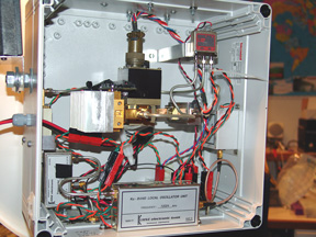
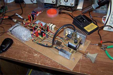
24 GHz portable systems get the OCXO upgrade....
DB6NT LO MODIFICATION - 5.7 and 10 GHz transverters:
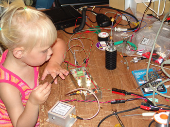
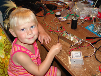
Jenna digs in....
I began to look into the modification from the DB6NT PDF manuals. These manuals for the MKU transverters were not exactly full of information in this regard. They noted the frequency and showed a capacitor to put in line with the LO input. They also showed the connection point on the schematic. That was about it though. For those experienced in these types of things, this would be enough. For a guy like me, I just figured I had to jump in to see what happens. All it looked like I had to do was to remove the crystal, and input the 1 mW LO signal via the capacitor. I obtained the correct capacitors and SMA bulkhead from DB6NT so I did not have to worry about that part.
I lowered over the MA-40 crank-up microwave tower and removed the equipment boxes for 5.7 and 10 GHz. The first one I started with was my 5.7 GHz transverter. It was a little bit of work to get the crystal out without damaging it for sure. Had to take my time and used plenty of solder wick braid. I got the hole drilled and the SMA bulkhead mounted. I used two screws only, and just a bit of solder on the bulkhead to the tin box to give a good electrical connection. If one drills the holes for the screws small enough, the screws make a nice tight connection as they tend to "self tap" into the tin box. So be sure not to drill the holes for the screws too big right away. That way you won't have to use nuts and lock washers.
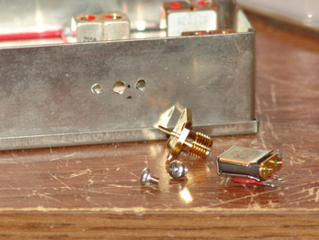
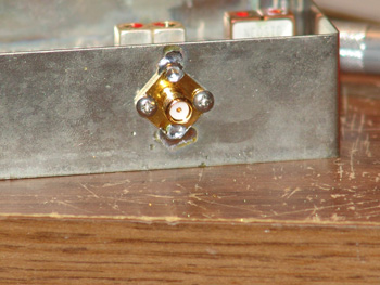
Mounting of the SMA Bulkhead...
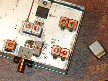
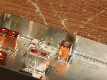
The NEOSID Brass tuning screw is on the left side of the SMA adapter...
After all that was done, I hooked some test equipment up and powered on. No RX noise.....hmmmm. Checking things over led to no changes needed. I was not sure what the problem could be. This got me digging into looking at the voltage test points on the transverter. According to the documentation, they were all out of whack. I then looked at the schematic a bit more. There were two capacitors in the crystal circuit that were in series to ground. Now that the crystal was removed, I wondered if these should not be connected to ground? I lifted the end of one and tested the voltages on the circuit board again. No change here.
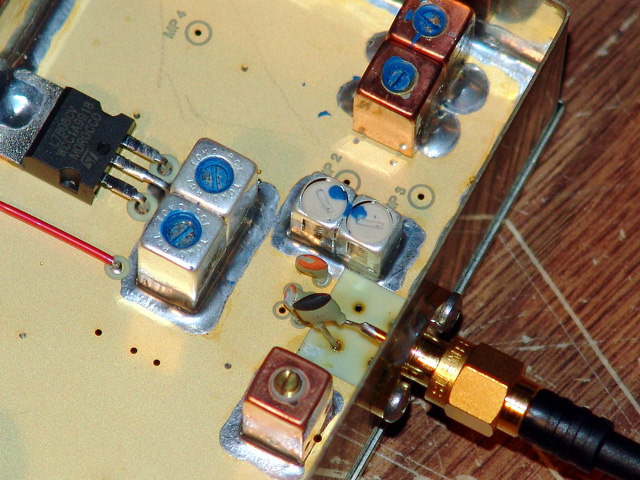
Capacitor input to the multiplier chain...
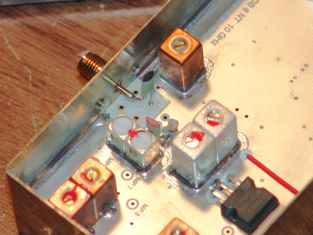
Another view...
So, was this not as easy as it seemed? I threw out a quick email to the microwave reflector and got lots of good feedback. I even got some good suggestions on how to "drive" the crystal itself without having to remove it. Great ideas and good feedback, but nothing that suggested anything I had done was wrong!
I then decided to tune the first bandpass filter for voltage test point M2, as that voltage was way out of sync with the documentation. Tuning this filter had little effect if not any at all. It would seem that in order for none of this to work, the crystal frequency and the external reference OCXO frequency would have to be very different, or the output of the OCXO was way too low. But everything was tested out prior to all this, so I was confident the OCXO was ok. I had also borrowed a frequency counter from one of my neighbors. He had just got a new B&K Precision hand held counter, never even used it yet. I just happened to be talking to him about what I was up too (He's a Ham too, 1 block away :) and wondering if the local college in town would borrow me one. He said "Hey, why not use mine!" Nice to be able to get a cup a sugar from your neighbor, and also ask, "by the way, how about borrowing that B&K as well!" Thanks Rich - N
ØOHO!
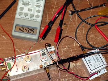
Feeding the10 GHz Transverter - OCXO at 106.5 MHz...
I sent an email out to DB6NT discussing my troubles and got one back a few days later. They said NOT to remove those extra capacitors and the only tuning required should be for the NEOSID brass tuning screw, which was for getting the original crystal to work properly.
With that, I went back and reattached the capacitor and started tuning the brass screw for testpoint M1. Sure enough, I began to hear a slight bit of noise and now the voltages started to come closer to what was specified. I then decided to hook up my weak signal source to see if the thing was hearing anything. When I attached a small loop antenna to the transverter RX port, the RX noise came way up! I let out a groan.....I had wasted quite a few days on this whole business, without having an RX antenna hooked up. If I had, I would have heard the RX noise right away and I would have been off to the races already.
A bit more tweaking and I tested for power output and got 250 mW, which was right on the money. The RX noise was good as the weak signal source was also sounding nicely in the transverter. At that point I put everything back into the tower enclosure and tested it all out. It was now time to get working on the 10 GHz transverter.
The 10 GHz transverter modification went pretty slick. Once all together, I just adjusted the brass screw slightly and the voltages were ok, but not on spec. I decided to tune the other bandpass filters a bit to get them closer. All tested well (I had a RX antenna on right away..) and I integrated the transverter and OCXO back into the tower box. This was very encouraging, as It was the end of June and I was running out of time. I still had to do the 5.7 and 10 GHz rover boxes for NØDQS's system.
I got the rover boxes from Gene the next day or so, and opened them up. I started to place the OCXOs in the boxes and came to the conclusion that they would not fit without a large amount of UT-141 recabling. I was a bit disappointed in myself, as I had build my tower boxes and rover boxes at the same time, but the layouts were slightly different. Apparently I had made a "running change" between making the tower systems and making the rover ones. I called Gene and let him have the bad news, I would not have time to do the OCXO integration on his rover system. Oh well, at least I knew "I" would be on 100.......
Daddy! It works!
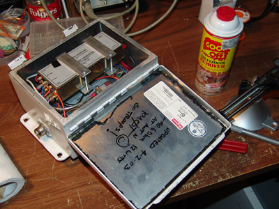
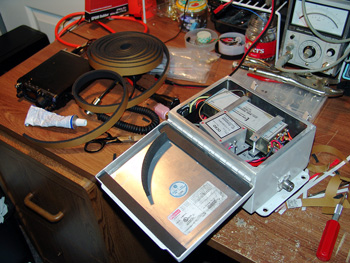
Keeping out the water!
OCXO Integrated into the 5.7 GHz tower box...getting weather stripped...
When I was doing the OCXO integration for the microwave boxes, it was apparent that the foam water seal between the cover and enclosure had reached the end of it's useful life. As the boxes were opened, the foam seals were stuck to the cover and tore in various places as the cover was forcefully lifted. Ahhh...just one more thing to work on...like I didn't have enough to do...
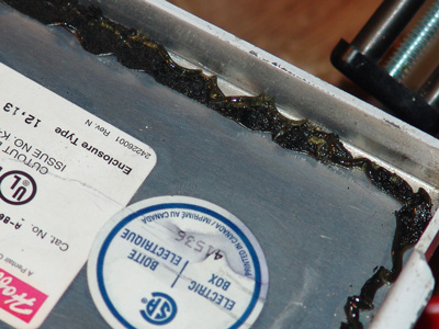
A trip to the local hardware store resulting in getting some foam weather stripping that might work. After that, I began work on one of the boxes. I scraped as much of the foam gasket as I could. But there was still lots of hard glue and foam stuck to the aluminum cover. I figured I could use my Dremel tool to wire brush it off, but all that did was melt it and did little to help. More scraping resulted in sweat pouring off my face and also produced a few bad words. I was into it now with no return, and still had 3 other boxes to work on!
I then found some "Goop Off" in the house and put some of that on paper towels. This gave some fair results, but it took lots of time to rub all the glue off. Once I got it done, I put the weather stripping on, but I was not too satisfied on how it looked. The standard window weather stripping from the hardware store did not seem to be quite the right stuff.
Goop Off...What marketing dude came up with that?
I slept on that for a day and then went to the local farm implement repair shop, Sioux Automation, for having some welding done for parts on my tower. (More on that later...) I happened to ask if they had weather stripping or something to that effect. What he came back with was exactly what I needed, nice thick and wide high quality foam at 40 cents a foot!
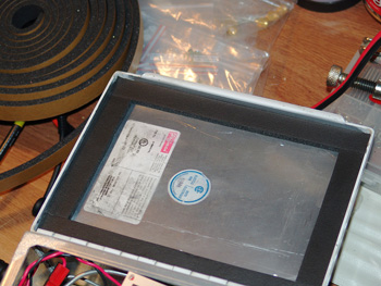
Cutting and pasting...
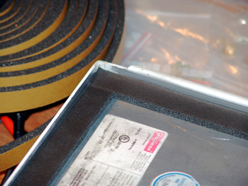
Corner detail...
That night I started to work on the next box, scraping and cursing the foam off the cover. I began to use the "Goop Off" when the kids upstairs were screaming about something. So I ran up there and had to settle the household down for about 20 minutes. When I returned, I was pleasantly surprised. What I had done before the kids started to make trouble was I poured some of the "Goop Off" on the cover. During the time I was gone, that stuff went to work on its own and pretty much just ate it all up! All I had to do was wipe it off! Patience is a virtue I'm told, which I have none...but it worked out this time!
WOW! This stuff works!
The new foam from Sioux Automation went on excellently. The other two boxes took only an hour apiece! I also tore off the weather stripping from the first box and redid that one too. Now things were ready to go back on the tower! If anyone wants to know the name or manufacturer of that good weather stripping seal, let me know and I will go find out!
TEST ONE TWO....
Another beautiful day in corn country...
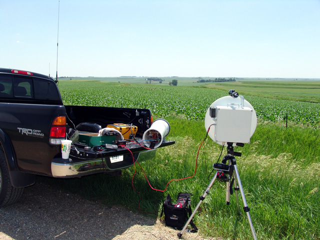
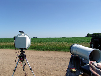
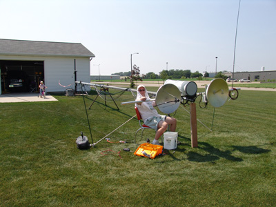
Portable 24 GHz and Tower System side by side...
The middle of June is when the 24 GHz tower system got completed. Now it was time to test. I happened to be going a bit south for a business trip around Holstein Iowa, which was not too far from Schleswig, Iowa where Gene - NØDQS lived. I hooked up with Gene and asked him if he had some time to test the 24 GHz systems. The idea was to get my portable system right next to the tower system in order to compare how well they worked. It was super hot that day, well in the 90s but the relative humidity was only about 55% with a fairly low dew point. This seemed like ideal conditions to do the testing. I was glad to have my work done early in the day, but when I got outside to play with the microwaves, it was pretty hot as I got a little sunburn on the back of my neck!
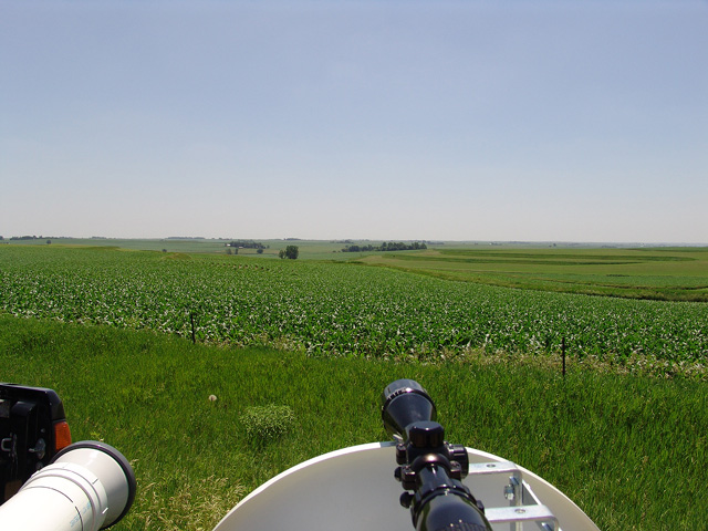
No mountains around here...but you can see forever!
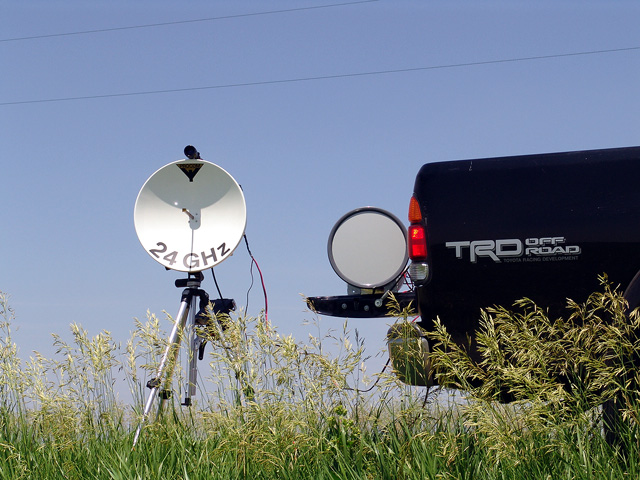
Gene and I started out about 18 miles apart. I had the tower system setup on my truck tailgate - adjacent my portable dish system. Gene was booming in of course and both units on my end were hearing about the same. It was hard to tell since we were so close to Gene, the Procom system seemed to be hearing about 1 S-Unit better than the tower system with the Lens Horn. The only thing I noticed was that the tower system was about 8 Kc low in comparison to the portable dish system. Strange I thought, as all were on OCXOs. Gene would keep his FT-817 IF rig on 100, then I would see how things would drift on my end. My dish and Genes dish were only a Kc apart, pretty normal, but again the tower system stayed about 8 Kc down from there. Drifting however was not an issue while we operated, so this was extremely fantastic to find out. We barely had to touch the dials over the 10 minutes or so at the 15 mile mark. This was a huge improvement, as before when the temps were as they were that day, we would have no idea where each other would be. We used to have to spin the dials to keep each other tuned when we did find each other!
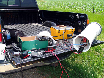
The "quick & dirty" setup mess on the tailgate...FT-817 IF radio...
At the 2nd stop of 42 miles, the Procom was only about a half an S-Unit better (Still S9+20). When I got to the 3rd spot at 74 miles, the units were hearing the same with S8 signals. All stops were pre-calculated so that Gene would not have to move his dish. I went to the new spots on the same heading, that way we could minimize any terrain differences to get a better feel for how the Lens Horn performed. All in all I was very happy how this initial testing went and was ready to move on to the next steps. I was quite impressed with the performance of the 250 mm Lens Horn antenna, considering how much smaller it was than the 48 cm Procom dish!
Horizon at 74 miles...slightly rising terrain didn't seem to bother us at all!
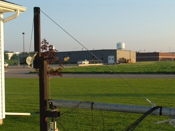
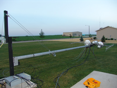
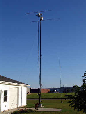
Tower Work
A month or so in front of the June Contest, I had to lay the microwave tower over for the renovation. I worked on this stuff in parallel with all the other things I had going on. There were a number of issues I wanted to resolve, as well as mount 24 GHz on this tower.
Note direct cable attachment to tower and rotating base...
Issues:
· Tower had too much play in it with the rotor mounted at bottom. The connection between rotor and tower had to be somewhat loose, otherwise binding would occur. Not good for precision microwave pointing.
· Tower was too wobbly in the wind. Not good for precision microwave pointing.
· Tower raised and lowered (from horizontal to vertical) too fast with one crank of the handle. Made me really nervous as the tower bounced on the cable!
Objectives:
· Mount new rotor at top of crank-up mast.
· Put a limited guying system on the tower just to keep it from blowing around.
· Fix or improve the tower raising system somehow.
· Mount the 24 GHz system on the tower.
· Pull off the 5.7 and 10 GHz systems and install OCXOs. Reinstall.
· Install a color camera on the tower.
Getting the CAD program going gave way to my ideas for implementing the goals.
The first thing done was to lower the tower down and get it laid over. At that point the entire assembly was removed from the top of the tower and set aside so I could work on the new rotor installation. So the 5.7 and 10 GHz dishes just sat on the driveway for the June Contest. However, I got to work on the OCXO installation as shown elsewhere in this write-up.
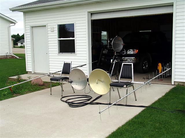
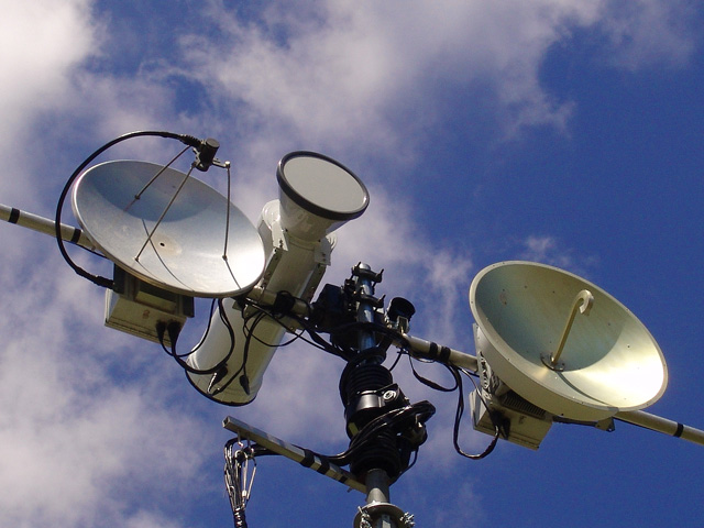
Dish array removed from the microwave tower...
The rotor I chose was the Alfa Spid. It had 1 degree resolution, was lightweight, and had no play in it. The day before Dayton 2005, I called up Jim – KØMHC to see if he could get me a “Dayton Special” while he was out there. However, he called me back and said they did not bring any out and just to call back to the store, as anyone who did would get the good pricing that weekend. Awesome, saved me some real money! So I got the rotor about a week later and dug up an old 28V power supply. The rotor sat around for a few weeks before I got it outside, but I tested it right away to be sure all was working.
Alfa Spid Rotor testing...
Once I got the rotor outside and began the initial installation with the control cable, I realized I was going to have to redo every RF cable, as they were not long enough to make a good rotor loop. Just luckily I had enough slack in my control cables for the dishes! That’s one thing I didn’t think of when I tore it all apart! “Oh well, too late now” I muttered to myself as I was cutting cables and removing hardware….
With the rotor installed and working, off to the next thing; fixing the tower itself. This I gave lots of thought too, asked lots of questions, and spent lots of time reading the varied opinions of guying a crank-up tower in the “Tower Talk” archives at www.contesting.com. The conclusions there were some against it, and some for it. However, the YEAs had some qualifiers. If you’re going to do it, don’t apply too much down pressure. If all your going to do is stabilize it, then your probably ok, but get a PE to certify the installation. Well, I decided to go ahead and guy the tower, but lightly as suggested, only to keep the tower from swaying.
(Now for the disclaimer: This is not an endorsement of this style or type of installation, you are on your own if you follow any of the ideas I have posted here. Get a professional structural engineer to analyze and certify your particular installation.)
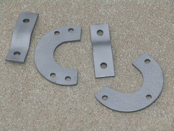
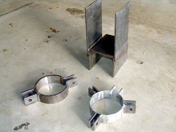
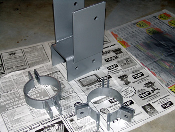
With that decided on, I needed some guying attachment brackets. I drew these up on CAD and had them manufactured by Sioux Automation here in town.
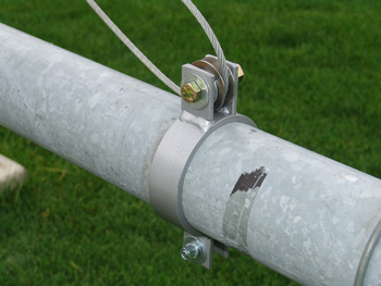
Bottom Guy Cable details and Pictures...
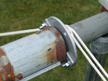
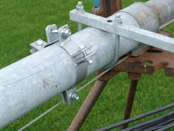
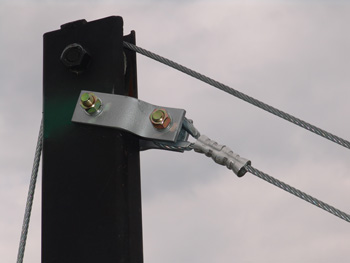
Top Guy Cable details and Pictures..."cable secure" attachment straps also in the left picture...
I then had to work on the tower raising feature. The cable went from the crank, to a single pulley, and then down to the tower's attachment clamp. I just wasn’t sure how to make this thing work any better. The cranking ratio was just too much in my opinion. However, it was the right crank for the job.
Note that this was a used old Wilson crank-up, which the MA-40 from US Tower was probably modeled from. So when I refer to the MA-40 crank-up, I’m really talking about my old Wilson. There are subtle differences between the vintages of towers. The pipes may be the same diameter, but the bolt patterns and raising fixtures are different. However, the US Tower and the Wilson had a bolted connection to the tower for the raising cable for their 40’ models. I snooped around the net and came across a number of crank-up tubular tower installations. What I noticed on the longer models, (55’ and 85’) that instead of having the raising cable attached directly to the tower, they had a pulley there and the cable was run back to the raising fixture. I talked to a few mechanically inclined folks and asked them what this did for the installation. (I must have been asleep in college during my Physics “Statics” classes.) Apparently this would take the strain off the winch, cables, etc. It would take twice as many turns with the crank to get the tower up, as it had to go through a cable twice as long via the pulley on the tower. So I had my answer and drew up a pulley attachment bracket for the tower on CAD. This too I had manufactured at Sioux Automation in town.
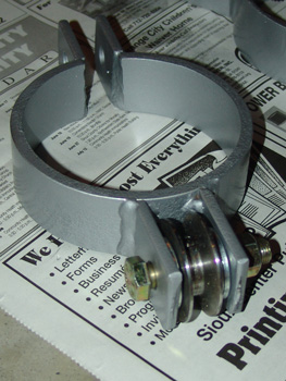
Pulley Strap Details and Pictures...
The last hurdle I had was to take off the rotating tower attachment at the base and replace it with some sort of bracket. Since I no longer would be rotating the tower, a solid bracket that would allow no play would be needed. All it would have to do is allow the tower to lower down to the horizontal position. Some head scratching and CAD drawing led to a custom bracket for that, again welded by the local guys in town.
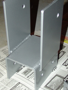
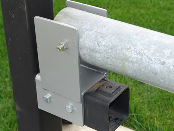
Base Support Details and Pictures...
With that, I needed to attach the cable back to the raising fixture. It seemed that the factory ones had the cable attached off to the side via a bolt through the upright, but I did not feel too good about that, so I drew up a quick plan for an extension out from the upright. That way the cable had a solidly centered pull without any sideways torque on the raising fixture.
Crank Cable Secure straps...
The results from the manufacturing were encouraging. A bit of grinding to take off the sharp edges and some paint was all that was needed. Here are pictures of before and after.
I got most of the above done right before the 4th of July weekend, where we all went to see my folks and other relatives...also took in a wedding shower...celebrated a few birthdays and drank some beer...boy did I need to "unplug" for a few days!
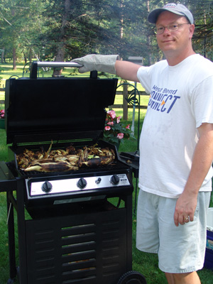
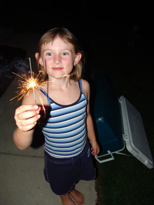
Cooking Corn at my folks in Breezy Point, MN & Patricia Celebrates the 4th!
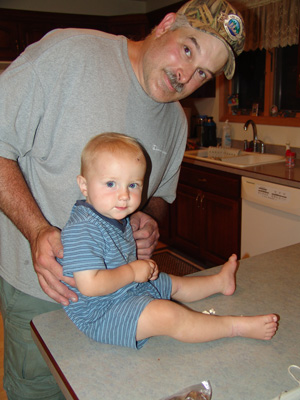
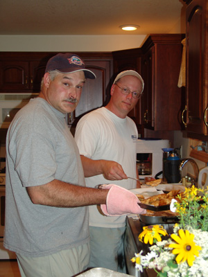
Matthew gets to hang with his Godfather Mike...then we cook Walleye!
(Gota love going home to Minnesota..)
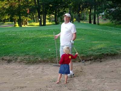
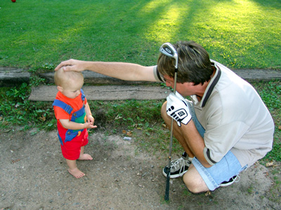
My caddie Jenna is ready with the sand iron....Matthew gets his first golf lesson...
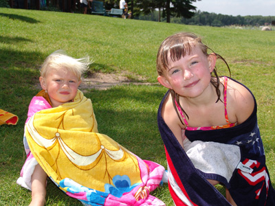
The kids got to swim and hang with Uncle Lonnie up visiting from 4 land...KG4BKV !
Back to Work!
After coming back from vacation, I got right back to things. Much to do and only a month to go...with everything else figured in for July and August, I only had two more full weekends to get it all going...
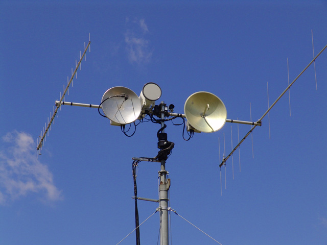
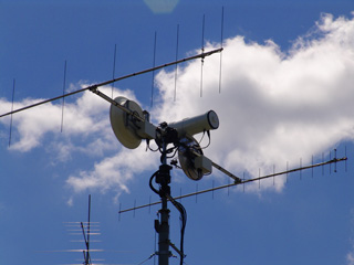
After the Alfa Spid Rotor got installed, the dishes got mounted back on the tower, now that the OCXOs were integrated. A few days were spent getting all the cabling back in place. New IF lines were run with RG-8X double shielded TramFlex. Before I had used a cheap Belden cable, and the shielding was not all that good. I spend considerable time testing the power at the ends of these cables, and keeping the lengths very consistent. That way with 3 watts out at the shack at 144 MHz, I was able to have 3db loss in the 5.7, 10 and 24 GHz IF lines. Everything on the tower was adjusted for 1.5 watts drive.
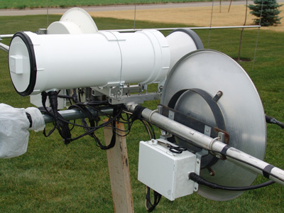
Finishing 24 GHz
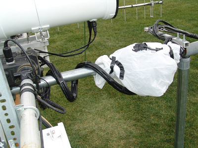
Now that the 24 GHz tower system had proved itself, I had to finish it up. I needed to mount the connectors for the IF, Power and PTT lines. A few nights of weatherproofing, sealing and painting were all that was needed.
Incoming lines weather sealed...
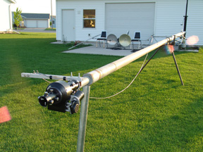
The next step was to figure out how to mount that thing on the tower. There were two steel straps I had mounted to the flange of the Lens Horn antenna, but these were not at the balance point and would not hold up if they were to be the only supports. While I was thinking about this, I had the XYL take a few pictures of me with the system. I picked it up and hoofed it up on my shoulder. My wife exclaimed, “Man that looks like some kind of bazooka!” I just grinned.
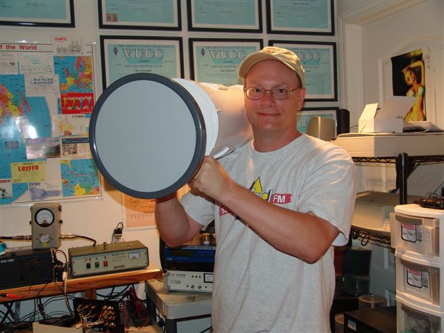
The "Gridinator"....not me, the thing on my shoulder J
A bit later when I was thinking of putting that picture on the website, I was wondering if something like this should have a catchy name. I though for a bit and as I was digging around, I came to see my “Terminator” DVD on a nearby shelf. Thus the “Gridinator” was born….
Mounting the "Gridinator"
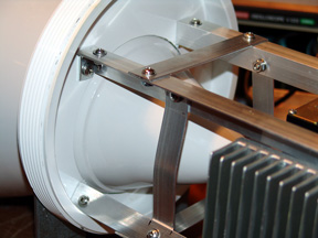
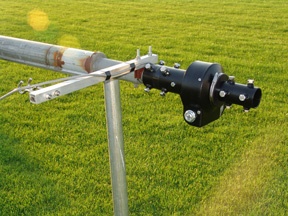
It looked like I was going to have to mount the boom clamps back a bit from the flange of the Lens Horn due to the balance point. So aluminum square was again used, as well as some 90 degree shelf brackets. I knew I had to get the back of the bracket somehow attached to the outside pipe, but I did not want to penetrate the plastic. Some digging around in some boxes came up with some mounting brackets left over from a “Jeff Kruth Special” 10 GHz button hook dish mount. This made up the space between the aluminum square tubing and the outside of the pipe. From there I decided to try a thin stainless steel cable attachment. This worked out great and when tightened down, gives an extremely solid feel to the whole assembly. The “Gridinator” was ready to make his move to the tower.
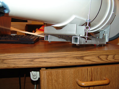
Mounting frame details and cable attachment...
I found the balance point and installed the mast clamps...
Final Testing!
Tower Raising:
Once the 24 GHz was mounted on the cross boom, I was able to finish the cable routing, taping, weatherproofing and all that other stuff one never thinks about. It had been extremely hot around these parts over the summer, and I had sometimes no choice when I could work due to other responsibilities….(i.e. seeing the family, eating, sleeping, work, etc.)
I came home one day a bit early from work to do some cable routing and the rotor loop, but it was so blooming hot, I couldn’t take it. So I went inside to do work in the shack, waiting for it to get cooler outside. Well, that didn’t happen until about 9:30 at night. I went out then and it was downright pleasant outside. So I hooked up a couple of construction work lights, my boom box and got my tools out
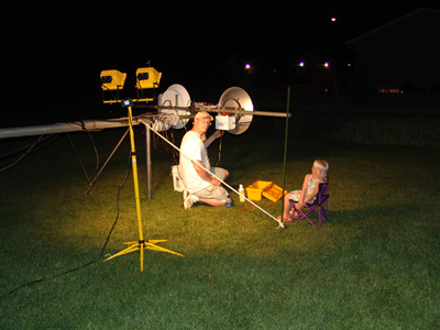
It's without a doubt past Jenna's bedtime...
I lit up the whole countryside it seemed. Boy did I get some strange looks I will bet from the cars going by, but it was dark so I could not see the expressions on their faces. I worked on stuff until 3:00 AM, so I was able to get a good chunk of the work done.
A few days later, I needed to finish up, but had no other time, so I had to brave the 100 degree temps. A towel on the head, soaked in water saved me from a trip to the hospital with heat stroke. It actually went ok; I just looked like a total dork. The looks from the street by passer bys were ignored.
The Shah of Sioux County...
Mounting details...rotor loop closeup...
Final testing having been completed, I needed to address one other issue. The Alfa Spid rotor uses bolts to attach the masts to it. These bolts stick out a bit, and I was afraid that they would tangle with the rotor loop coax. I thought about how to block the coax from hitting the bolts, but I could not come up with anything that I thought would work. I then wondered if some 4” PVC couplings cut in half and then taped together around the bolts would work as a shield. As I was getting ready to go to the local hardware store to walk the isles and think about my problem, I came across some old drain tile piping lying in the corner of the garage. “Hey I wonder if I can split that down the side and maybe that will slip around the bolts?” It was a lot cheaper than cutting up some PVC couplings! Well, that worked like a charm.
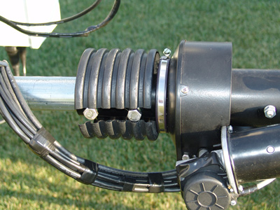
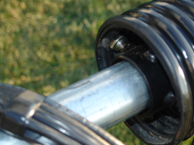
Drain Tile Pipe covers over the Alfa Spid bolts...
There was about 1” spacing once I slipped it around the bolts, so I cut another piece and slipped that around the first piece. The 1” spacing actually worked out as when it was turned, the bolt heads on one side fit right in there and kept it from turning. Electrical tape was then used to secure the two pieces together; it all fit like a nice glove and worked great. Alfa Spid Users take note!
I also had time to get a color CCD camera on the tower. I cobbled some old TV antenna brackets together and figured a way to attach the camera with a U-Bolt clamp. The camera did not have a sun shield, so I cut an old beer cup in half and painted it up to protect from UV. It almost looks like it was made for it!
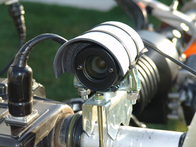
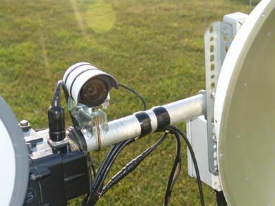
Camera is fed by RG6 to a small 5" LCD in the shack...470 lines res...does a good job!
All ready to go, now to cross my fingers!
A few days went by and I waited for the wind to die down. The tower raising went well, albeit I was a bit nervous as the extra weight from the Alfa Spid and the “Gridinator” were now at the top of the tower. The pulley system worked just fine. It seemed to take the stress off the raising winch in comparison to what it experienced before with the direct connection to the tower.
Once the tower was up, I was able to spot my guy point screw-in anchors and made the attachments to the lower set. The upper set would be attached once I cranked the tower up to its full height.
Ready for Action!
Note guy attachment points...
After all that business was done, I had time to switch my digital voltmeters to analog counterparts. These meters were used to monitor the relative voltage outputs from the 2.3, 3.4, 5.7 and 10 GHz transverters and amps. That way I knew things were working upstairs. The digital meters seemed to constantly need calibration as the 9V battery that ran them got weak. So I had some analog meters in a box and decided to get those mounted on a piece of plastic surface raceway. The raceway came as a sample from Panduit, and was going to get tossed in the trash. That came home with me as I figured someday I would find a use for it :)
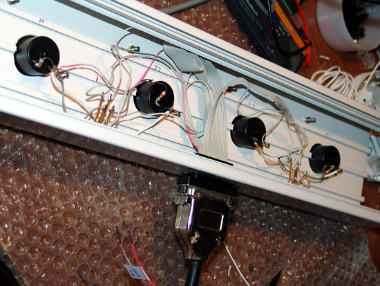
Just a bit of measuring, drilling and filing was all that was needed to mount the meters. I then scrounged around for how to connect this mess. After looking at a number of different ways, the easiest was to use an old computer parallel cable and computer parallel adapter ribbon connector. That made things very easy to trace and connect!
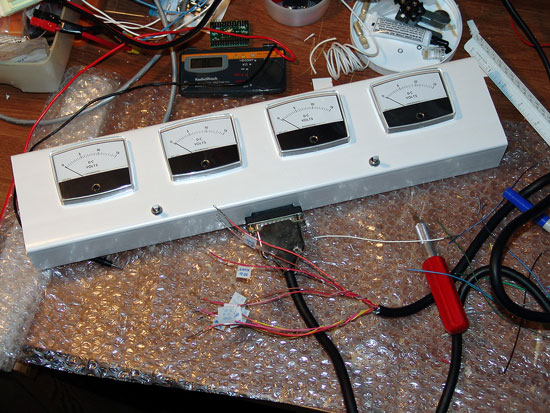
From left to right, 2.3 - 3.4 - 5.7 and 10 GHz voltage monitors...
The switches are used to monitor the transverter or power amps. Each switch is a double pole double throw, so the left switch controls the left two meters, and the right switch for the other two. It worked really well and looks good too!
Working on the SDR-1000 and UCB
Along with all the other things I had going, I was working closely with Flex Radio on the initial implementation of the UCB designed by Tony - KB9YIG. With the UCB - Universal Control Board, I wanted to be able to switch bands by hitting a button on the SDR-1000 software screen. There were lots of issues to work through in terms of the software implementation of these features, but Eric at Flex Radio pulled together a pretty good simple control software package right before my going to Central States. With that in place and working, I was able to finish another Power Point presentation that Terry - WØVB and myself were going to show off at the conference. See the KMØT SDR-1000 part of the website for details.
The UCB implementation at ARS KMØT...
Colorado Springs
!!!! – CSVHFS
The Hospitality Suite at CSVHF Colorado Springs...loads of fun!
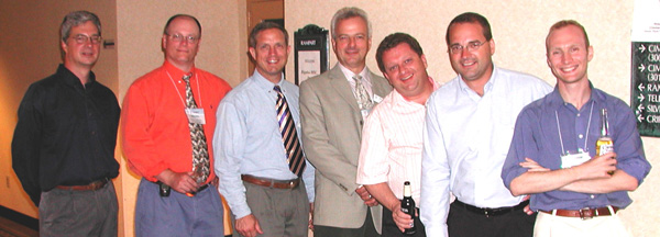
Jon -WØZQ, Mike - KMØT, Bruce - W9FZ, Peter - VE3AX, Chris - NØUK, Matt - KFØQ and Andy - KØSM
Photo by Unknown...W9FZ's Camera
There was a number of late nights spent up to this point, so going to the Central States VHF Society Conference was going to be a bit of a rest….NOT!
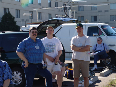
KMØT - KØSM - KFØQ - Photo by W9FZ
The Antenna Range at CSVHFS!
As mentioned earlier, I had obtained two of the Lens Horn antennas for 24 GHz. I brought one of the Flann Microwave Lens Horns to the conference, where I was going to get a look at its gain. The Lens Horn was rated for 21.2 to 23.6 GHz, and 34 dBi of gain. At 24 GHz, Kent Britain - WA5VJB measured it slightly more than that rating. I was very satisfied that this antenna was going to work out, as for when I compared these gain figure to the Flann Microwave information, everything seemed to agree.
Gene - NØDQS, yours truly and Jon - WØZQ
The Banquet at CSVHFS!
At the Banquet: Andy- KØSM hangin with my XYL Colleen...
Barb - XYL of Jon - WØZQ and Dave - NØKP on the right.
Photo by W9FZ
For those of you not familiar with the Central States VHF Society, check out the website. It is a fine organization and does lots to promote the type of operating that we do. Get involved and join CSVHFS. You will be glad you did! Next year the conference (2006) is in Minnesota. Bloomington, a suburb of Minneapolis is where it will be held. The Thunderbird is the hotel, adjacent the Mall of America! In 2007, the conference will be held in San Antonio.
There was also a bit of Rover Mania planning going on at Central States. The hospitality room was full of guys talking about lots of different things, however if you looked close, there were always a few NLRS guys talking in the corner J
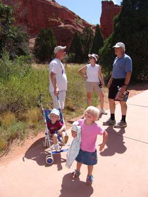
When we left the conference on Sunday morning, we stopped by the "Garden of the Gods", a city park in Colorado Springs. Boy, we could have spent the whole day there! Lots of neat things to see.
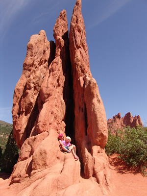
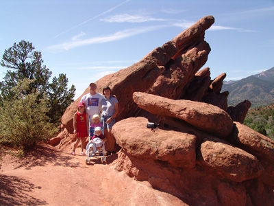
The color of the rocks is awesome...it truly is a "Garden of the Gods"
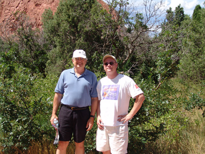
Ran into David - K1WHS and his XYL while out hiking the paths...
"David, I need some more blowtorch loopers" - "did you bring some?"
When we got on the road northeast of Denver, I had the old rig on 144.200 and heard Gene - NØDQS calling CQ. He was very loud so I figured he must be close. However, he was about 100 miles away up about 14,000 feet! Elevation helps! The rest of the trip was pretty uneventful, other than working W4WA from EM84 on SSB via 2 Meter Eskip! Not bad for 50 watts and a single HO loop!
KØSM Visits the Homeland (Again)!
Andy – KØSM came home from college for a summer visit to his folks in EN10. Andy’s idea was to do some roving for the UHF contest while he was in the area to take part in Rover Mania II. The plan was for him to come up to EN13 on Thursday before the contest to get outfitted once again.
I had 95% of the things I needed completed and ready right before I went to the Central States convention. This was important, as I had to be in Des Moines for business pretty much that whole week before the contest. I was not due to get home until Thursday afternoon. That worked out well however for timing and when Andy arrived, we got to work right away.
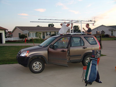
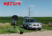
KØSM/R getting ready for battle...
Thursday Night:
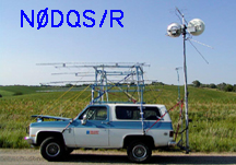
On Andy’s way up, I coordinated with Gene – NØDQS and Andy to meet somewhere out in the fields of Iowa corn to do some equipment swapping. Gene had a 222 MHz and 902 MHz antenna for Andy to borrow, that way we would not have to spend the time building “cheap yagis” this year. This of course saved us lots of time.
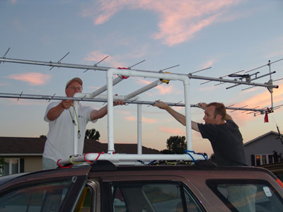
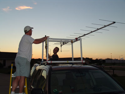
432 yagi being installed...
When Andy arrived with his dad’s car and the PVC rack we built for Rover Mania I, we got the antennas mounted and feedlines run. I had to make a feedline for 432 MHz and it tested well with Andy’s new 432-9WL. Andy purchased that at the flea market at Central States, and took the front half off the antenna to make it more suitable for “Rover Use”. A bit of tweaking the match got the SWR all in line. We also mounted Gene’s F9FT 902 MHz yagi. The thing looked pretty beat up, but it's all we had. We also mounted Gene’s old 222 MHz boomer, in anticipation of the 222 MHz transverter showing up via UPS. After getting the good old 3456 MHz 112 element “blowtorch” looper out of storage, it was time for a few pictures of course. Depending on the weather, we were not sure if we would participate in the contest or go golfing. But we had the clubs out just in case.
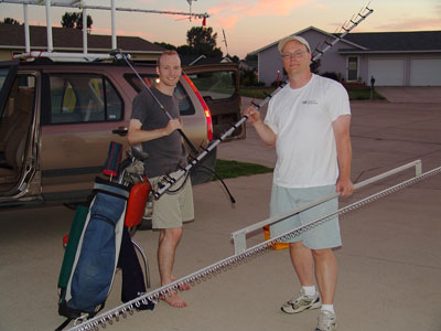
Rover Mania II or Golfing....hmmmmmm...A blowtorch is kinda tough to putt with...
Friday:
I managed to slip out of the office mid afternoon, and we started to coble up the gear. Reports from last year were such that the guys that borrowed the DEMI 902 MHz transverter I built said “it wasn’t working”. I got it all set up on the bench and hooked up some test cables, power meter, etc. Sure enough, the RX noise was low and the power output was around 2 watts. Uhhhhggg…like I didn’t have anything else to do. Andy came over to look over my shoulder, or to give me re-assurance since I think he heard the expletives fly. As he did so, I moved something on the bench and for a second, the RX noise really livened up! We sat there in silence and looked at each other briefly before we both started jiggling cables and such. Sure enough, the IF cable from the FT-817 to the transverter had a broken or cracked center conductor in it. This was a brand new factory made jumper cable – N to SMA I had gotten off of eBay (go figure) but it had come in a factory sealed bag! We replaced the cable and I retested….10 watts and Good RX noise. One more crisis averted! The transverter was working as it should and the guys last year must have had a poor antenna and feedline.
We then tested the 3456 Rover Box that I had built some years ago with the 15 Watt DB6NT amp. (about 3 months before PyroJoe came out with his 40 watters…man that still hurts…..) All was good there and I was off to rig up one of my IF switches.
The IF switch I used for switching between 50 and 222 MHz during a previous shack layout was available now since everything had been redesigned and newly configured. Since we had just two bands to switch, this was a perfect fit as it needed no AV switchbox to control, just press a button and IF and PTT was automatically routed. It had two relays to do split IF, but we only needed one, so I just hooked up half the box. This fit nicely into Andy’s Rovership and once all the cables were tied down, things got powered up and tested. No Cops this time as Andy did not get pulled over by the locals during his shakedown cruise. ( I think he was a bit disappointed actually….)
The 222 MHz transverter still had not showed up. UPS got lazy apparently and left the box sitting in a warehouse. Numerous calls to SSB Electronics and the UPS reps resulted in some call backs from actual UPS employees. They assured me that it could be delivered Saturday morning. My guess is that it would not work out. I jokingly mentioned to Andy, “yeah, it will be here about a half an hour after you leave”.
After that, it began to get dark. So I had Andy help me with the tower for a while. I got the microwave tower cranked up and rigged out the guy wires. Andy held the guys as I put on the clamps and we put a slight tension on the upper guys. Again, this was not to keep the tower from falling over, but to just keep the upper section from blowing around in the wind. I did not want excessive “down force” on the tower or raising cable / winch.
During the evening, Andy played with a bunch of microwave components and tried to rig up a 1296 transverter. We had a bit of trouble with that as it turned out, the mixers were for a completely different band. So that got shelved for the time being. Later that night I configured my FT-100 (liberated from my truck) for being used as the IF for the 222 transverter. Since it was a split IF device, I had to rig up a TR relay to split the IF coming out of the FT-100 and configure PTT and power lines. That all got tested out and was ready to go should everything fall into place. It was pretty late and off to bed. I never got time to rig up my beacon keyer….next year perhaps.
Saturday Morning:
A good nights rest was well received. I was in pretty good shape, just a few do dads to do and make sure “Roverlog” was up and running. We had something to eat and waited as long as we could, the 222 transverter had not showed up. Andy had to get going if he was going to make his scheduled 12 grids. With that, were tore off the 222 MHz antenna and retested the 432 MHz system. That was acting weird. Some SWR adjustment to the match got everything back in order and Andy was on his way. The 222 MHz transverter showed up an hour later…..akh! Who wudda thunk UPS worked on Saturday….
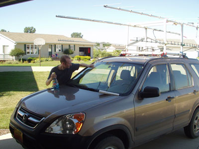
Final Rover Servicing...
The Contest Begins in the Microwave Playground!
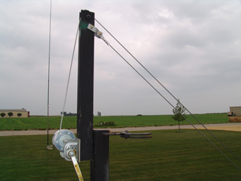
Cranked up and ready to go...
A few minutes before the contest, I got hold of NØDQS/R out west as he was setting up in EN03. We got the antennas peaked on 10 GHz and noticed he was having some audio issues with some of his equipment. Gene indicated that he would look into it quick, so I told him I was going to swing to the NE – as WØZQ/R was to be in EN33. I wanted to get a heading on him prior to it all getting going.
I got hold of Jon – WØZQ/R and we started to get things lined up. Then I heard Gene off the back of the beam as he said he was ready to test things out. Boy, the juggling had already started before the contest!
Anyway, I got Jon zeroed in and made note of the Alpha Spid rotor degree heading. I told Jon I would be back as soon as I could to work him, hoping that the beam heading would be repeatable on the Alpha Spid rotor.
As I swung back, Gene and I then decided to see if the 24 GHz was working. I found him no problem as the contest began, the “Gridinator” had it’s first kill! We worked through the bands, still with his audio issues on some bands and hoped he could find a quick way to work it out.
I needed to get pointed back to WØZQ/R as I was sure he was waiting. That’s when Andy – KØSM/R called in. I quick worked him on his 5 bands and then swung back to Jon. WØZQ/R was there and we quickly worked up the bands. Now for the test of 24 GHz, Jon’s first contact on the band. It was well over 100 miles, so I was worried that pointing might be a problem.
As it turned out, Jon was pointed right on the money and the SDR-1000 saw his signal right were it was supposed to be! The initial first two contacts with the “Gridinator” up on the tower happened so quick I did not have time to think about it! Wow, the headings for the 10 and 5.7 GHz antennas when peaked on both Az and Elevation were also lining up the same for 24 GHz. Six months of work was finally vindicated…..it had all been worth it.
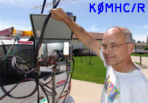
KØMHC/R – Jim came blasting in from up north in EN25. We quickly worked on all bands, not trying 5.7 and 10 GHz as he figured the 150 mW he was running would probably not make the trip. (Wish we would have tried, because we had no problem every time we did try when he made it to the other grids.)
I then picked up Clair – KØCJ in EN34 for my first home station. That ended the first hour of the contest, it was fast and furious, now the grind would begin. I figured that with most rovers I could find in their first grids done, then the rest of the contest would be much easier juggling where everyone was.
After Gene – NØDQS/R was in EN02, he started to have problems with his 1296 MHz system. Stike 1 again! For some reason he could not hear me and I could not hear him. We both argued that we had just got done working someone else on 1296, so “my system” was working, well you know the story... Gene was pretty frustrated as he was experiencing this and was still having some audio issues here and there.
I then worked Jon – WØZQ/R in a few grids, and on 1296, so I swung back to tell Gene the bad news about “his system”. Well, he had worse news for me than I had for him. His AC clutch V-belt pulley wheel had sheered off the spindle, and the others metal pulleys were threatening to do the same thing. Strike II! He was headed for the home QTH…ARRGHHG! Luckily, he headed back home via the grid corners by my place and I was able to work him while he was in motion on all the bands except the blown 1296 and of course the portable 24 GHz….that truly was a bummer. He said if he was able to nurse it home, he would quick look it over to see if he could get it running for Sunday. With other rovers waiting, I had to say “good luck, hope you make it” and spun the dial….he understood thought….at least he said he did.
I juggled rovers for the next couple hours, swinging back and forth from the west, to east to north and back again several times. This was not as easy as I had hoped. The QSOs were going fine, it was just taking time. During all this, nothing had been heard from the south, but as I was looking east, W8MIL and a few others started to pop in around 2200 UTC. “Wow” I thought, “this must be just an anomaly….”
Well, over the next eight hours, I worked out east several times. If I had not been juggling the rovers, then I could have made tons more QSOs out there I’m sure. Stations out farther east that were worked were W8MIL, K2YAZ, N9TZL, K2DRH, W9UD, WO9S, K8TQK, K9MRI, KC9BQA, WA8RJF, N9DG, K8EB, WW8M, KB8U and K8MD. Good signals were had from a few on 2.3 GHz. The band was open, but nothing was happening above that as I was unable to QSO on 3.4 GHz with anyone out there. How exciting it was thought, some REAL DX for the contest! I even heard Jon – WØZQ/R having a pileup of eastern stations on him. I had to spin the dial as I knew he would be busy for a while! All the time I figured I would run into Bruce - W9FZ/R in the EN40s and EN50s, but not a peep was heard.
Between trying with the guys out farther east and juggling the rovers, other locals started popping in. Jerry KØCQ was in there from EN32, Dave – NØKP from EN34 and Jon – WØAMT. Jon was not out roving this UHF, so it was good to catch him at home. KCØLXB was also in there from EN34 around 2120 UTC.
I got a call from Gene – NØDQS/R. He had made it home, but his rover 4 wheel drive had locked up, now in full time 4WD. This was a problem…Strike III. - YOUR OUT! ARGHHGH!
The multi-ops were worked on the lower bands, NØHJZ in EN34 and K9CVC in EN44. I heard these guys on and off all contest, so that was very good to see. Gary – WØGHZ was finally caught up with around 0440, and worked up through 5.7 GHz. Dave, NØKP tail ended on 5.7 GHz, so that was pretty cool. Marc, WBØTEM in EN12 got on late night and ran what bands he could muster up. His rotor was stuck to the SE, but no matter as we were able to go up with what he had running. Thanks for jumping in there Marc! I know he ran into some of the rovers too!
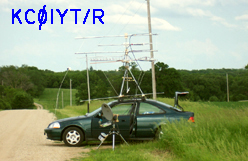
Around 0130 I finally ran into Glen – KCØIYT/R in EN25. That was good as it finally meant I could start to track him for the next grids. However, Glen and I were not able to link up reliably throughout the rest of the contest. A few QSOs were had him after he made it to the next grid, but that was about it. I then heard he was having alternator problems. Looks like we had to scratch another rover...
Like I said, I figured the juggling would get a bit easier, but man was I busy. Between Andy – KØSM/R, Jim – KØMHC/R, Jon – WØZQ/R and the calling out east…there were not too many blank minutes in the log book. However, the SDR-1000 IF on 902 and up was humming along and made the microwave QSOs easy pickins, literally. I would ask the guys to call me, I would see them, pick em with the mouse and work em. Then hit the UCB band button for the next band and off we would go to the next band. When the rovers were out a ways, I could typically work them on all bands in about 5 minutes or so. What took the time is for when the Rover’s left their vehicle to man the GHz dishes.
The SDR-1000 with the UCB on 902 thru 24 GHz was responsible for 142 Grids and 273 QSOs....
It never blinked and ran flawlessly throughout the contest...Thanks Flex Radio!
Andy made it back home to EN10 about 0500. He picked up his Dad, John - NØRHL and I had a family rover situation for 3 QSOs anyway. Thanks John for riding along a bit! After that, Andy started to make his way back to EN13 via some new multiplier grids!
Things did manage to slow down a bit in the wee hours, but I was still plenty busy. I spent the extra time CQing to the south and southwest towards N0LL, but Larry was not home I think. I also spent lots of time CQing due north and to the NE for EN37 and Bill – KØAWU, but I never heard him the whole contest. It really seemed that the propagation was below a horizontal line that ran mostly parallel along EN15, EN25 to EN35. Paths from down here north of that line were not heard to be open. I worked very few QSOs north of that line. Sorry Bill, I was looking for you! I was also looking due north as mentioned before for VE land. Just earlier in the week I worked Bruce, VE4KQ in EN09, but nothing heard over the contest weekend. I knew Dennis, NTØV in EN08 was on too, but not a peep there either. I tried these paths in the twilight too thinking that the early morning propagation would be good. But the wind picked up a bit as light came and blew any chance of that away. It also squashed the long paths out to the east, as lots of RF was sent that way hoping the band would pop open again. Nothing heard however. Where was Bruce – W9FZ/R? Also, never heard Matt – KFØQ/R – he was over there somewhere too. I recall hearing guys working Ken – W9GA I think in EN54, but even with my yagis pointed right at him, I could not hear a thing. It just seemed that there were some definite boundaries to the propagation.
I had picked up Jon – WØZQ/R 6 times with the “Gridinator” on 24 GHz, but as time rolled on and he got farther than 125 miles, we were not able to make it on that band anymore. Incidentally, I was pretty sure I heard him one time, but so weak I was not able to make it out. The humidity during the beginning hours of the contest was in the 40 to 45% range. As night rolled along, the humidity steadily rose and temperature stayed about the same, so the water content of the air increased considerably. I noticed as I tracked W0ZQ/R though the first 4 grids on 24 GHz, the distances remained pretty much the same, but the signals got progressively weaker. I’m pretty sure water vapor losses were the culprit here, but it was fun to try.
On 5.7 and 10 GHz however, signals were banging in. Jim – KØMHC/R, with his QRP 150 mW dual band dish, did a bang up job and was worked in all his grids except 3. These were his far north grids. Andy- KØSM/R with my borrowed 5.7 / 10 GHz dual bander never had a problem in his 12 grid stint. Jon – WØZQ/R for his 12 grids was also never a problem with his 6 watt 22” offset dish on 10 GHz. On 5.7 GHz, he was running 2 watts from a DEMI transverter, but into a large 21 db horn antenna. He was weak in a few grids, but never a problem copying him at all on CW. We swept on all bands for 12 grids except for 24 GHz. I also managed to get hold of the NØHJZ multi-op on the low bands for coordinating 10 GHz. That worked out great! It took a few tries for them to get their dish un-obstructed and pointed in the right direction, but when they did, I was really banging in there. Apparently I was 30 over 9 or so! Rich, NØHJZ had never had a QSO on 10 GHz SSB, so we had a nice chat! They were coming in down here about 5x7, good solid copy. It’s amazing what a few extra watts on 10 GHz can do for a guy!
Around 6:00 AM local, I was getting pretty tired. I had not even thought of sleeping all night, as the adrenalin was pumping pretty good. There was a small lull in the action and I was getting sleepy. I kept the headphones on and laid back for a bit in the chair. I think I snuck in 15 minutes or so until I heard Andy – KØSM/R calling on 432.100 for me. He said he had not heard me for a while and wanted to make sure I was not slackin off on the job sleeping….so much for the nap!
I brewed a pot of coffee and kept chasing the rovers. Between them and a few stragglers here and there, the morning was somewhat productive. I picked up Bob – WØAUS on a few band, but boy the band was dead to EN35. It was also weak to KØFQA also in EN35, but we made it on 432 SSB. I managed to eek out John – K9JK/R in EN43 while he was in motion on 222, but that was it. The contest ended with a brief opening again out east, as I was able to work K3SIW in EN52 on 432 CW. We tried on 222 but no joy there. I then worked my first EN45 QSO of the weekend, KB9TLV on 222 right at the end. However, the contest was over and I slumped back into my chair, the juggling was over!
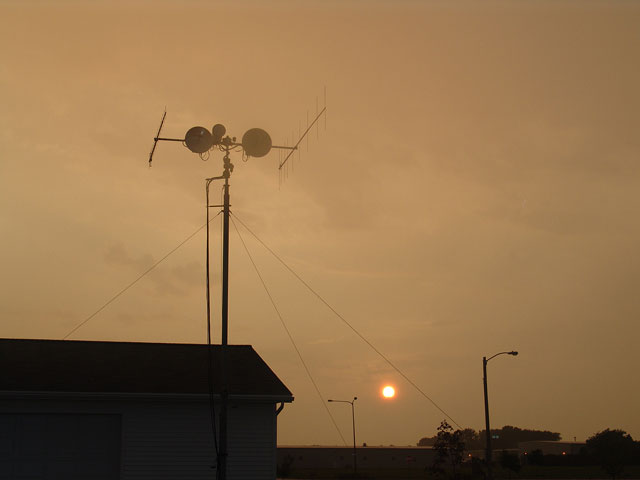
Evening falls on EN13vc after the contest....smoke still rising from the 10 GHz dish.....
|
Band |
QSOs |
Pts |
QSO Pts |
Grids |
|
222 MHz |
58 |
3 |
174 | 31 |
|
432 MHz |
76 |
3 |
228 | 33 |
|
902 MHz |
55 |
6 |
330 | 27 |
|
1296 MHz |
40 |
6 |
240 | 23 |
|
2304 MHz |
39 |
12 |
468 | 22 |
|
3456 MHz |
48 |
12 |
576 | 22 |
|
5760 MHz |
41 |
12 |
492 | 20 |
|
10 GHz |
42 |
12 |
504 | 20 |
|
24 GHz |
8 |
12 |
96 | 8 |
|
Totals All Bands |
407 |
|
3108 |
206 |
KMØT CLAIMED SCORE: 640,248 SOHP
Wow! It turned out really really good. My best score yet. Wonder what the score had been if Gene - NØDQS/R had made his 12 grids without car and rig troubles! Also, wonder what kind of QSOs I could have gotten from Bruce - W9FZ/R if I could have found him. He was up in the forests of Wisconsin, so that made things pretty tough to find him.
Multipliers were up significantly on the high bands, this was the key to the score being so much higher. The extra 45 QSOs dint hurt either :)
3456 MHz was again the winner band with 48 QSOs and 22 Grids, by far the best overall score contribution. Folks got to wake up and get on this band. A looper from Directive Systems combined with a 40 watt PyroJoe amp can give an op quite a thrill ride! 3456 MHz is the best kept secret other than 5.7 GHz, another rockin microwave band that always seems to work!SUMMARY CONTESTS PAST
| YEAR | SCORE | QSOs | GRIDS | PROPAGATION | ACTIVITY |
| 2004 | 349,020 | 361 | 140 | POOR to FAIR | GOOD Due To RM I |
| 2003 | 127,008 | 168 | 112 | POOR | FAIR to GOOD |
| 2002 | 54,288 | 104 | 78 | BAD - WX | POOR DUE TO WX |
| 2001 | 138,312 | 184 | 136 | AWESOME | GREAT DUE TO TROPO |
I would characterize this years propagation as poor to fair. The fair comes from the brief tropo opening out east, otherwise it was pretty dead. The grid count was way up. Most of that was due to all the rovers, but there were significant multipliers had from the tropo opening to the east. In addition, local fixed station activity was low as lots of ops were roving. Also, some of the locals usually heard were not around for some reason, so lots of fixed station QSOs were missed.
Comparisons to 2001 are interesting. If "Rover Mania II" (and "Rover Mania I" for that matter) could have happed with some good tropo conditions, can one imagine what kinds of multiplier and overall scores would be generated!! Note that in 2001, 136 multipliers were had and a pretty good score was generated. The rover QSO percentage in 2001 was only 28%, so that really tells you how wide the band was open. Put those two combinations together and one could really do some damage. Incidentally, I have never had propagation during a contest like it was in 2001, so it was pretty special! Just as it happened last year, It appeared the week before the contest this year that tropo was a possibility, but it did not pan out and we were right back to typical windy warm and dry weather. Next year hopefully!!! Thanks everyone for all the QSOs!!!
"The Rover’s Corner" ©
WØZQ/R wins the Rover's Corner Award!
What can I say, “Rover Mania II” was the key! Here is the chart of Rover activity I worked:
| BAND | WØZQ/R | KØMHC/R | KØSM/R | NØDQS/R | KCØIYT/R | NØRHL/R | K9JK/R |
| 222 MHz | 12 | 12 | 6 | 4 | 1 | ||
| 432 MHz | 12 | 12 | 12 | 6 | 4 | 1 | |
| 902 MHz | 12 | 12 | 12 | 6 | 3 | 1 | |
| 1296 MHz | 12 | 12 | 2 | 3 | |||
| 2304 MHz | 12 | 12 | 6 | 3 | |||
| 3456 MHz | 12 | 12 | 12 | 6 | 3 | 1 | |
| 5.7 GHz | 12 | 9 | 12 | 6 | |||
| 10 GHz | 12 | 9 | 12 | 6 | 1 | ||
| 24 GHz | 6 | 2 | |||||
| Total QSOs | 102 | 90 | 60 | 46 | 21 | 3 | 1 |
Total Rover QSOs = 323
Rover QSOs % of Total QSOs = 79% WOW! The rovers really were the major key even though the QSO count was a bit down! After looking at the list of rovers that had intended to participate, (some had equipment and other logistical problems) It looks like I could have had a bunch more rover QSOs in the log.
A special thanks to all the rovers. Without contacts from them, the score would be next to nothing! "Rover Mania II" was a complete success!
Below is a chart of last years "Rover Mania I" Rovers. As one can see, there were lots more rovers.
|
BAND |
WØZQ/R |
KØNY/R |
KBØTHN/R |
WØAMT/R |
KØSM/R |
KØPG/R |
K9ILT/R |
|
222 MHz |
12 |
10 |
10 |
8 |
|
3 |
3 |
|
432 MHz |
12 |
10 |
10 |
8 |
6 |
3 |
3 |
|
902 MHz |
12 |
6 |
6 |
8 |
|
|
|
|
1296 MHz |
12 |
6 |
6 |
8 |
|
|
|
|
2304 MHz |
12 |
|
|
8 |
|
|
|
|
3456 MHz |
12 |
|
|
8 |
6 |
|
|
|
5760 MHz |
9 |
10 |
10 |
|
|
|
|
|
10 GHz |
12 |
9 |
8 |
|
4 |
|
|
|
24 GHz |
|
|
|
|
4 |
|
|
|
Total QSOs |
93 |
51 |
50 |
48 |
20 |
6 |
6 |
|
BAND |
KFØQ/R |
NØHJZ/R |
KCØP/R |
NØHZO/R |
WBØLJC/R |
|
|
|
222 MHz |
4 |
8 |
|
|
|
|
|
|
432 MHz |
4 |
8 |
1 |
1 |
1 |
|
|
|
902 MHz |
4 |
|
|
|
|
|
|
|
1296 MHz |
4 |
|
1 |
1 |
|
|
|
|
2304 MHz |
4 |
|
|
|
|
|
|
|
3456 MHz |
4 |
|
|
|
|
|
|
|
5760 MHz |
|
|
|
|
|
|
|
|
10 GHz |
|
|
|
|
|
|
|
|
24 GHz |
|
|
|
|
|
|
|
|
Total QSOs |
36 |
16 |
2 |
2 |
1 |
|
|
Total Rover QSOs Last Year = 331
| YEAR | R-QSOS | % | ACTIVITY |
| 2005 | 323 | 79 | AWESOME!! |
| 2004 | 331 | 91 | AWESOME!! |
| 2003 | 118 | 70 | GOOD |
| 2002 | 71 | 68 | LIGHT |
| 2001 | 52 | 28 | LIGHT |
Above is the chart of the Rover activity over the last few years.
We hope this will give the ARRL something more to talk about in terms of UHF CONTEST ACTIVITY. It is ALIVE AND WELL!!!!
Oh, and for those of you who think this was a big grid circling expedition by all the rovers or captured rover situation, well - go pound MORE sand! The rovers were all independent entities, and they were not captured rovers until I could find them! They all came up with their own routes and did what they wanted. From what I have read, there were fewer "Rover to Rover" QSOs made this year, so there was no grid circling going on around here!
GRID CHARTS
This was the second contest where I used "RoverLog" (It's just not for Rovers ya know!) and it worked out very well. I also decided to do a slightly different custom grid map layout. I used the "RoverLog's" notation for indicating the general number of QSOs in a grid to show activity level from each area on each band. "RoverLog" has a map function that shows this as well on the fly so one can check on the QSO density as the contest progresses. The program worked very well and I will use it again! See http://roverlog.2ub.org
Green Grids are one contact.
Yellow Grids are more than one and less than five contacts.
Red Grids are five or more contacts.
No laser this time again and only 8 grids on 24 GHz. Gene - NØDQS/R had car trouble once again and I was only able to get 2 grids on 24 GHz from him. If he could have hung in there, the "Gridinator" would have picked up at least 2 more grids from Gene! Man that would have been awesome! Thanks to Jon - WØZQ/R for giving me the other six 24 GHz Grids! Now do you understand why I call this area the "Microwave Playground"?
One can see from the extent of the grid maps, we had a brief tropo opening out to the east, that was a fantastic bonus! Too bad the tropo did not hold, as it was in and out here in EN13 for about 8 hours.
Well, better propagation next time hopefully - one of these days it will all come together!
73 and See You Next Contest!
Mike - KMØT EN13vc