24 GHZ at ARS KMØT
Caution! Lots of pictures....be patient and hit "refresh" if all the pictures don't show up. Hopefully it will be worth your wait!
Introduction:
The thought of going to 24 GHz was far from my mind back in the summer of 2002. We had just come back from the Central States VHF convention in Madison Wisconsin where I had done a bit of chatting about it, but nothing serious. With Jenna just being born, I was pretty busy with family stuff. I recall a few guys giving me a hard time about it, and me saying "not for a few years yet".
As the winter bore down, things were pretty well getting on line with raising the kids and I did manage to find again some spare time. I recall giving Donn, WA2VOI a call on the phone about 24 GHz and the ins and outs of it. Having no idea what or where to start, Donn gave me lots of good ideas and told me about where he and Bob - WØAUS, were at with their 24 GHz project. That kind of got me fired up and I began to do a lot of research on the Web as well as do some talking with Gerry at SSB Electronics. Gerry also put me in touch with Walt, WA1HHN. Walt had built a few 24 GHz stations for their contest group and I began emailing with him back and forth. Walt had lots of info and was happy to share it.
I also got in touch with Paul Drexler, W2PED. Paul was resource for 24 GHz power amplifiers I was told. Amplifier projects were being done over there for the Pack Rats and Microwave Update members, and Paul was involved with that effort. Here is a link to that story.
Without all the help from these fine folks, this project would not have turned out as well as it did. Thank You!
Research and Gathering of Materials:
Waveguide.....
I first started out by spending a month looking for WR-42 waveguide pieces and parts. Not a whole lot to be found on ebay. But there were a few waveguide manufacturers that had lots of good info on WR-42. I gave a call out to Penn Engineering in California and spoke with one of their waveguide salesmen. I indicated that I was a "Ham" and was considering getting on 24 GHz. So after we chatted a bit, it was decided that he would send me some parts of pieces of waveguide, flanges, etc. Kind of a sample pack so to speak. It turned out to not be too expensive as he gave me odds and ends from the scrap bin.
One thing for sure, knowing that I would need some WR-42 waveguide to SMA type transitions, I checked on prices of these commercial units. Very expensive, in the $250 to $300 range. So I opted to look for other methods.
Waveguide Transitions.....
I came across an interesting article in one the Microwave Projects manuals by the ARRL. Kent Britain, WA5VJB had written a short report on how to home brew 24 GHz waveguide to SMA transitions. It was republished in the projects manual from its original publication in the one of the "Microwave Update" Proceedings.
Anyway, it looked relatively painless on how to home brew a transition, just needed some WR-42, a WR-42 flange and then a SMA Teflon covered probe. Here is a diagram from the original publication.
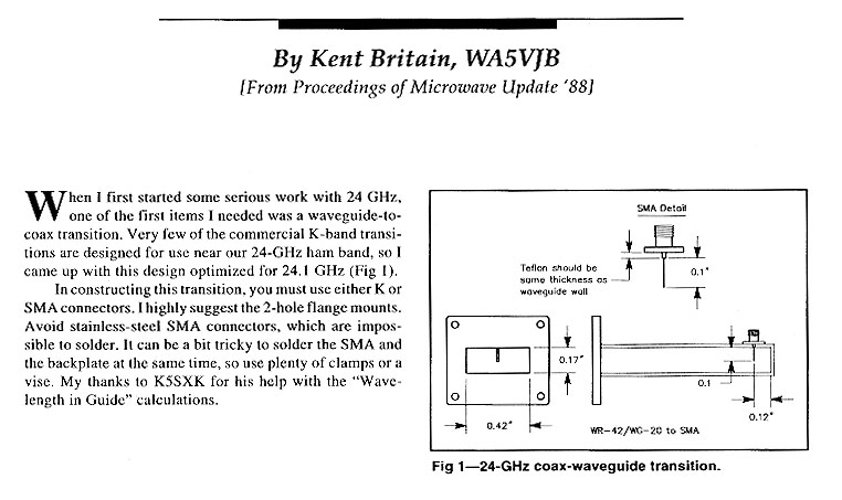
I also emailed a bit with Kent and got some more specific information. Kent had some good extra info and with that in hand, I picked up some Teflon covered SMA probes from The RF Connection out east. Joel was very helpful and got me the probes in no time. I then began to attempt to build some of these units.
Knowing that the measurements were to be fairly precise. What I needed was some kind of caliper. I went to a local tool dealer in Sioux City and they showed me what they had. I then asked if they had a digital one. The guys said sure, but they were more expensive. I looked over the unit they had and it sure seemed to be what I needed. However, at $100, it was more than I wanted to pay. I then looked at the cost of commercial transitions and decided I better get the meter. I quizzed the salesman about the price and asked him if they were cheaper somewhere else, etc. Nope, these were the new thing and actually this was "inexpensive". So I bit the bullet and walked out with the digital caliper.
That night I was not feeling too good about how the salesman had dealt with me. I went to ebay and punched in "digital caliper" and got tons of hits back on the search. Well, there was my digital caliper for sale, brand new, from about 30 different sellers. The price was around $28 bucks on a "Buy It Now" basis. The next day I made a trip back to Sioux City and returned the one I bought. Got one the next week from ebay, same exact thing, plus extra batteries, never been opened, etc. Guess I will always check there first.
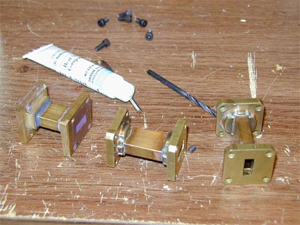
With the parts in hand, I made a jig for drilling and started to get a feel for how close I could get. I made 4 units and they all seemed to turn out a bit different. I was being careful as I could, but it was hard to avoid. Here are a few pics of the construction.
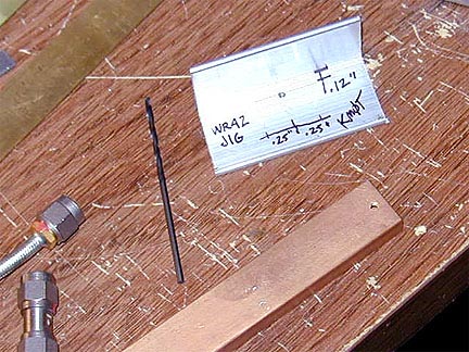
Jig with WR-42 - SMA connectors show relative size.
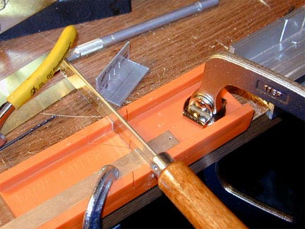
Cutting the WR-42 with a razor saw and small miter box. Razor saws can be found at hobby stores, etc. Get the one with the most teeth per inch. If you go slowly, it makes a nice clean cut. A micro miter box is a must.
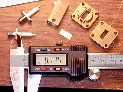
Here is the caliper showing overall rough probe length with Teflon. Note the waveguide piece, flanges and home brew end cap. Getting the hole drilled in the waveguide in exactly the center and exactly the correct distance from the end cap seems to be the hardest part. See the awesome $28 digital caliper. Don't pay $100 in the stores! Beware!
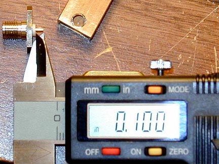
Probe length as it extends beyond the waveguide thickness. Teflon only extends the depth of the waveguide wall. Cut a bit long and trim with a file to get .100 length. This seemed to be fairly painless, but takes good peepers to eyeball the caliper and probe length.
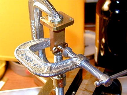
C-Clamps hold the parts together prior to applying the torch! I just used regular old electronic solder. I cleaned the parts good first so the solder would take quick. Tried to get as little solder on the end cap as to not get a big pool of it at the end of the waveguide. The flange was soldered first, separately from the rest, allowing it to cool completely prior to the probe and end cap attachment. If you go quick on the bottom, the flange original soldering does not seem to be effected when working on the probe and end cap. The torch used was a standard propane head, but Mapp gas tank, the yellow one. This gas burns a bit hotter than propane stuff. Not sure it really makes any difference however as I did not use a roaring flame out of the nozzle.
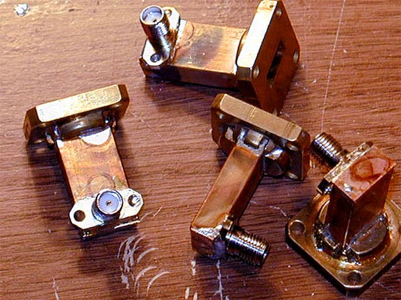
Here are the finished WR-42 to SMA adapters. See, they all look just a bit different and work a bit different from an electrical standpoint. More on that later.
Power Measurements at 24 GHz.....
Power measurements at 24 Ghz from what I was told was a critical part of the setup. I had purchased the DB6NT 24 GHz transverters and they had a very low rated power output. In addition, power input to the 24 GHz amplifier was critical according to Paul - W2PED. (More on the amps later)
Gerry at SSB Electronics indicated that one could use the transverters as they were factory set, just needed to drive them at the exact 144 MHz level as was indicated on the data sheet. But having no idea what the cable losses were of UT-141 and SMA connectors at that frequency, it would be hard to determine on paper.
Others told me that my HP 435B meter would work, but I would need the proper sensor head that was rated over 24 GHz. Using my 10 GHz head would result in too much error to set the proper levels. Searches on ebay resulted in some frustration as the power sensors that were rated where I needed them were very expensive. Also no guarantees on if they would be DOA or not. Heads from commercial vendors were even more expensive, but guaranteed to work.
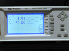
So I ended up making a deal with a vendor on ebay who had a Gigatronics 8651A Universal Power Meter and 10 GHz rated head. He happened to have a 80313 head that was rated to 26.5 GHz on auction at the same time. So I called him up and discussed the equipment options with him. He ended the auctions and swapped the heads. The meter arrived in fine shape and was ready to be put to the test. The 80313 head had a male K connector and could take power levels up to 800 mW or +29 dBm. The K connector mates mechanically just fine with an SMA female barrel.
Anyone else who wants to use the meter, just let me know and If I am in the neighborhood......
Initial Transverter Testing.....
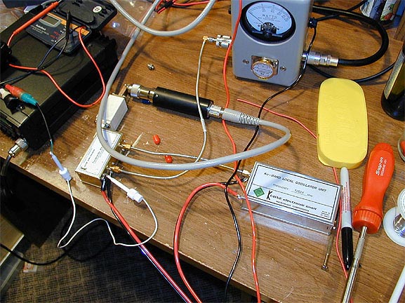
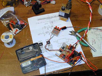
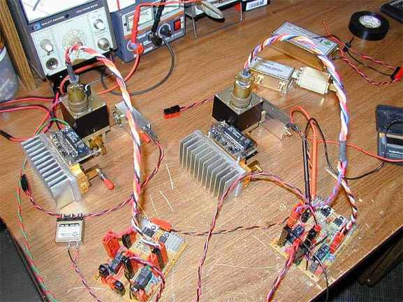
With the power meter in hand, I bench tested the two DB6NT transverters. I ran all the tests with the 2 stage image filters attached to the end of the transverter waveguide output. The transverter specs were such that they put out 0.4 mw for unit number 1 and 0.35 mW for unit number 2. This was factory set by the internal drive level pot - 2.5 watts drive at 144 MHz.
With that information, I measured the power output thru the image filters using the homebrew SMA to WR-42 transitions.
Here is a picture of the bench testing.
Transverter #1 - rated output 0.4mW @ 2.5 watts drive = -3.98 dBm.
Power measured: -7.99 dBm (homebrew transition #1)
So loss thru the image filter #1 was 4.01 dB
Transverter #2 - rated output 0.35mW @ 2.5 watts drive = -4.56 dBm.
Power measured: -10.62 dBm (Homebrew transition #2)
So loss thru the image filter #2 was 6.06 dB
The variance of 2 dB seemed to me to be caused by the construction of the waveguide adapters. In fact, I did the same test with homebrew adapter #3 and got a -12.3 dBm reading, a 1.68 dB worse reading from adapter #2. So I could definitely tell that the construction techniques were the culprit. I felt that the image filters should be very close in terms of losses.
In addition, I measured the dynamic range of the potentiometer within the transverter. I was able to vary the power output of transverter #2 from -23 dBm to -8.96 dBm. (All thru adapter #2) So the dynamic range was in the 14 dB range. (Again all at 2.5 watts drive @ 144 MHz)
Due to the variance, I obtained some commercial waveguide adapters from SSB Electronics. These units were manufactured by Procom out of Denmark. These adapters come with a sweep sheet from a network analyzer. It shows the response over the K band. I then compared the commercial unit to the homebrew adapter #1 (which showed the best results) and came to find that the Procom unit provided a .95 dB better output than homebrew transition #1. Given that, figuring backwards, it would appear that the image filters give about a 3 dB loss. This seemed reasonable, so I moved on from there.
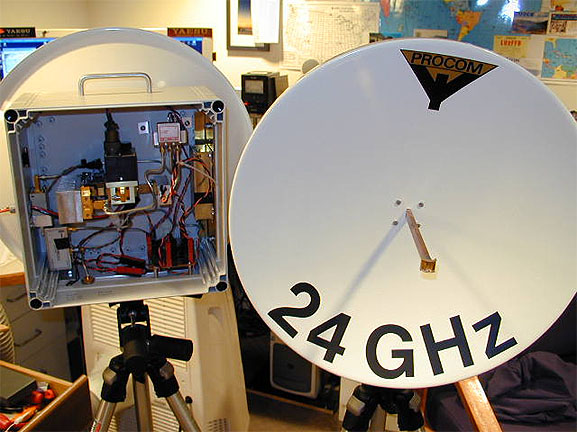
Here are a few pictures of the commercial adapter from Procom. These are about $85 from SSB Electronics. Compared to other commercial adapters, these are a real bargain. Plus, they are tuned for 24.192 GHz, which would not be the case for standard K Band adapters.
With the time and materials it took to homebrew some adapters, it would be a toss up. But with no real way to test them here, and the fact I tried to make them all the same and they did not operated that way, I decided to go with the Procom units.
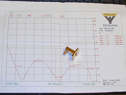
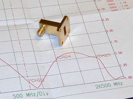
Note the SWR figures at Channel 23 - 1.14 to 1. Channel 23 is 24.192 GHz. Boy, don't they look a lot like the ones I built!
Other Component Measurements.....
I then decided to measure some other components to get a feel for how they were for loss at 24 GHz. I set the output of one of the transverters to a nice even number and then inserted various components in-between. Here are the results.
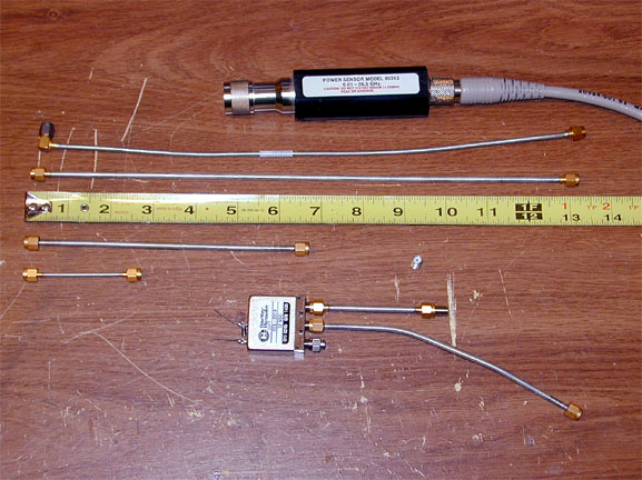
Measurements:
| Cable | Length | Connectors | Other | Loss - dB |
| UT-085 | 3" | SMA | SMA Female Coupler | 1.7 |
| UT-141 | 3" | SMA | SMA Female Coupler | 1.0 |
| UT-141 | 6.5" | SMA | SMA Female Coupler | 1.4 |
| UT-141 Flex | 13" | SMA/SMA 90 | SMA Female Coupler | 7.5 |
| UT-141 | 13" | SMA | SMA Female Coupler | 1.9 |
Note that all cables were commercially manufactured. Fairly old stuff with some center pins tarnished. The flexible UT-141 showed the most loss for sure. From previous experience, this cable even exhibited some pretty good loss at 2.4 and 3.4 GHz, so I was not surprised at the results for 24 GHz.
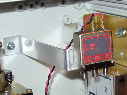
I also measured a brand new DowKey #401-2208 SMA relay that was rated only to 18 GHz. I ran a 6.5" piece of UT-141 from the transverter to the common on the relay, then a 3" piece of UT-141 from the NC contact to the Gigatronics sensor. (Also the SMA female to female coupler was in there)
After taking into account the cable losses, the relay calculated out to have a loss of .63 dB. Not too bad I figured and I now had a fairly good feel for the various component losses.
Now I know that these are not exact figures, but it was the best I could do with the limited test equipment I have. Perhaps this basic information will come in handy for some folks.
The Design…
After some discussion and reviewing the DB6NT recommended layouts, I felt that the advice I received from Gerry at SSB Electronics and Walt, WA1HHN was the way to go. Here is a picture of Walt - WA1HHN sitting next to WB3FKQ who is holding their contest group's 24 GHz Rover setup.
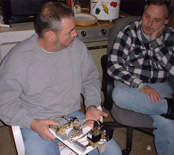
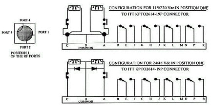
The basic advice was to use a 4 port waveguide switch, but only use it as a single-pole double-throw device. This took a bit of thinking on my part as I have not been around the RF stuff all that long, but I began to pencil it out and it really made sense. All that one had to do was to also switch the 24 GHz RF out of the transverter before it reached the power amp and preamp. Here is a block diagram of the design.
Now the SMA relay is not rated at 24 GHz, and the connections are made with UT-141, but there is quite a bit of "throw away" available. Gain from the pre-amp on RX would be more than enough. Also, the drive level required for the power amp was very low. Even with the losses, the transverter's output might still be too high. I was told I would probably need an attenuator.
However, I did not need to deal with those issues right away, just to be aware at this time. What I really needed was to decide on a basic design and concept in order to figure out what other materials I needed. I could then also start thinking about control of the whole contraption.
Waveguide Switches
.....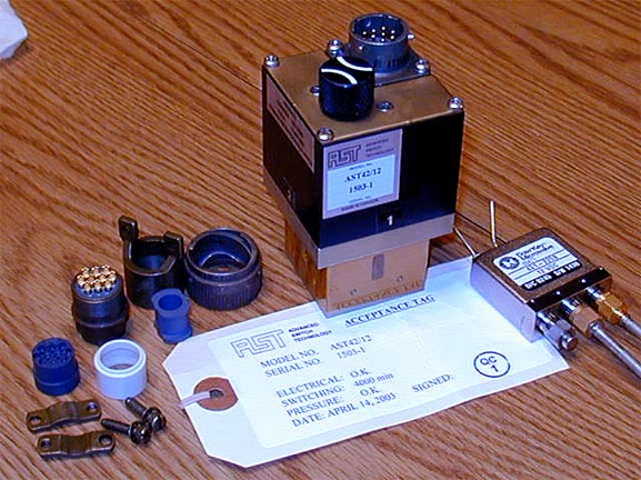
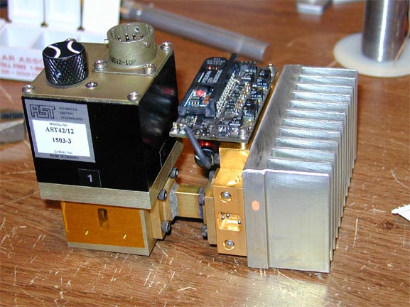
Well, that left me to find a waveguide switch. I searched in vain on ebay, nothing to be found. I looked around other sites, nothing there either. So, on the recommendation again from the guys out east, I started looking at Advanced Switch Technology out of Canada. They had a waveguide switch that was WR-42 in size and could be manufactured with 12V control. These switches also have internal dry contacts that give feedback on the switch's port positions. This feature turned out to be a great asset.
The switches feature a "power off" condition that when you apply the 12V to one set of contacts to make it switch, as soon as it transfers, the power disconnects. That way there is no continuous power draw to the coil. So in effect, they are latching devices. You simply apply power to one of two sets of contacts to make it switch back and forth.
The switch came very well packed and was very high quality. Also, the connector hardware for the multi-pin connector was all included. They also have a manual turning rotor that allows one to manually run the switch back and forth.
Here are some specs…Again, check their website for more details.
| Connection Type |
WR-42 |
| Operational Frequency |
18.0 - 26.5 Ghz |
| Return loss |
-26 dB typical |
| Isolation |
60 dB min |
| Insertion loss |
0.1 dB |
| Power handling |
1 kW CW max |
| Driving voltage |
Lots of choices |
| C form contacts |
2 Sets |
| Power connector (included) |
ITT KPTO2E12-10P |
Here is the wiring diagrams and dry contact info...
So, the model number I ended up ordering was: AST42/12. Walt - WA1HHN was instrumental on hooking me up with AST and in fact, I was able to route my purchase through his contracting house, "HHN Electric". This did indeed save me some money and Walt was very good about everything in terms of the time commitment to re-mail and do the paperwork, etc. So if your interested in this, they are available at a better price in quantities. I believe the price break is at 4 units. Email Walt for details. WA1HHN@aol.com
Power Amplifiers.....
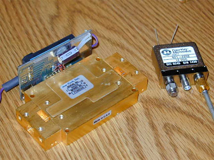
After emailing back and forth with Paul Drexler, W2PED. I decided to go with the mm-Tech 24 GHz power amplifier. This unit was apparently made for commercial use, but some were made available due to specification changes by the customer. This left a number of units up for surplus. Paul spends some time retuning them for 24.192 GHz and makes them available for amateur use. The amplifiers are of very high quality and represent probably the best bang for the buck when it comes to power on these high bands. A very good value and Paul is very fair with what he charges.
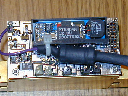
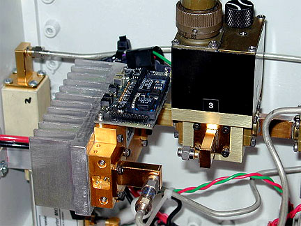
Both the input and output are WR-42 waveguide and attached with 4-40 screws. For approximately 33 dBm output, they require a very little amount of drive, around -20 dBm. This awesome little guy puts out 2 watts at about 1.2 amps. Voltage range is approximately 8V to 15V and has voltage regulator on the bias board to get the voltages just right to the internal MMIC devices. A heat sink is definitely recommended. Some type of sequencing was also suggested.
+VDD is the purple wire with the coil attached. The ground connection is the pin just above it.
Here is a link to a PDF file on care and use of the mm-Tech amplifier by Paul Drexler, W2PED.
Receive Preamplifiers.....
While I was doing the gathering of materials, DB6NT came out with a new line of K Band receive preamplifiers. The units I ended up with were the MKU 243 RX2. These units have a WR-42 input to the preamp and a SMA connector on the output. Noise figures from the data sheets I got with the preamps indicated 1.15 and 1.45 dB. Gain was 27 dB and 30 dB respectively.
With units as hot as these, I started thinking about my past experiences of blowing preamps and front ends. So proper sequencing of all this stuff weighed heavy on my mind.
Control and Sequencing:
With the sequencing issue at hand, I spent considerable time thinking about what needed to be done. Also, Walt – WA1HHN discussed his sequencing methods with me. He used industrial style relays that were connected in a cascaded fashion in order to get his timing issues worked out. Again, all in an effort to sequence the power to the power amp and receive preamp in conjunction with the RF relay and waveguide switching.
I on the other hand have had good luck with the SEQ series of electronic sequencers from DB6NT. These little guys are not all that expensive and seem to work great. I decided to take a hybrid approach with relays and a SEQ2 sequencer. The relays were needed because the DB6NT 24 GHz transverter does not have a +12V output during transmit. This is a bit different from other DB6NT transverters, where they all have this feature. Because of that fact, the sequencers require a +12V to make them go into operation. Another relay was needed to swap back and forth the power to the waveguide switch. NO / NC contacts worked great for this.
I first started out by looking at the timing diagrams for the DB6NT SEQ device. I then came up with an expanded timing diagram to see how it was all going to work out. Here is my version of the timing diagram.
In conjunction with the sequence timing diagram, the schematic / block diagram for the control circuit flowed along with it.
One real nice thing about the waveguide switch was the internal dry contacts. I was able to use these to turn the receive preamp on when only in the RX position. As soon as the waveguide switch thinks about going to TX, it breaks the contacts and turns the power off to the preamp!
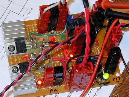
Here are some pictures of the completed control boards. They aren't pretty, but work very well!
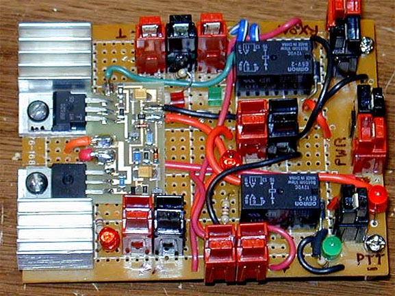
I had to build the control boards prior to getting everything else together, so I felt that going with a modular approach was a good idea. Everything would connect to this board with the exception of 12V for the transverter and LO. The power pole connectors made it ideal for testing and was a snap to install. This will make it easy to remove, repair and replace if needed.
The connector on the lower right (black) is the PTT input (ground). When ground is present, the green LED will light.
The connector to the left of the PTT (the double red) is connected to terminals D and E on the waveguide switch. One routes +12 to the contact and then back down. When it gets back to the board, the +12V is routed to the red/black in the upper right hand corner. That is connected to the RX preamp.
The red/black on the lower left is for the connection to the PA. The red LED adjacent lights up when the sequenced +12V becomes available from the SEQ2.
The tri connector red/black/red in the upper left is for connection to the waveguide switch control, A, B and C. Where B is the common, black connector in the middle. The green square LED lights on RX, the red square LED lights on TX.
The connector between the relays is for the SMA relay connection, along with its associated red LED.
Relay number 2 is on the top, relay 1 is by the PTT input.
When powered up, the red LED near the far right "PWR" power-pole lights up. Also, the green square LED lights as RX is the default position. (NC contact of relay 2 gives +12V to A-B of the waveguide switch)
When ground is attached to the PTT input, then one sees the green PTT LED and red SMA LED light up as the square green one turns off and the square red LED lights to indicate the TX position. Just a brief second later, the red LED near the power amp connector lights. One can definitely see the progression of the sequence, and its great for trouble shooting. On release of PTT ground, the whole thing reverses for the most part. The green PTT LED goes off at the same time the PA power LED turns off. Then the SMA LED goes off and the waveguide green LED turns on. All back to the receive state.
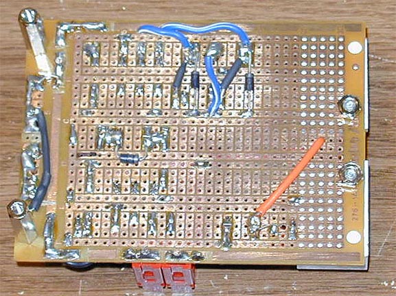
Here is a picture of the bottom of the board. Note the suppression diodes for the relay solenoids are mounted here. Its kind of nice, just replace the relay if need be, no need to put a diode on. Power pole connectors were put on by soldering #14 AWG solid into 25 amp power pole pins, then drilling holes the correct size and spacing. Once soldered, snip off the extra. They hold very well, but still need to be a bit careful as to not tear the foil off the board.
Assembly of Components:
Now that the major things were figured out, basic testing completed, it was time to assemble the whole thing and see how it all fit together.
Cables.....
As one can see, lots of little cables had to be made. Since I was building 2 dish setups, that was kind of nice having it all standardized. That way I could swap a cable, board, amp, switch, etc. as needed to test or replace. It was a tedious process making these things, but old lengths of rotor cable came to the rescue for the wire supply!
Waveguide Sections.....
Some I built myself, and a few I managed to scrounge after a bit of looking around. Note the tape on the ends. That's to keep the drill bit metal shavings out of the waveguide as I drilled the mounting holes out a bit. Anyone who has soldered a pipe can handle making these with no problem.
Heat Sink for Amplifier.....
A picture is worth a thousand words.......just be sure to use one! I conned the wife around Father's Day to get me a big blade chop saw. Made cutting the heat sink material a piece of cake. I tried earlier with a "Sawzall", man what a mistake. My hand razor saw...well forget that!
Final Basic Assembly.....
All wiring harnesses tested with their respective control boards. This was the status one week before the end of June. It was a good time to take a break as my wife Colleen was slated to run in Grandma's Marathon over the June 21st weekend and the Hoffman enclosures had not showed up yet.

It was her 4th Grandma's and 11th Marathon overall. She did not have as good a finishing time as she wanted, but hey, she sure did not keel over! (like I would have) It was a beautiful weekend in Duluth and was good to get away and "clear the mind".
One of these days she will qualify for the Boston Marathon. When that happens, I will be coming out there! Lookout!
Monday the 23rd came along and I had everything I needed. So I began slappin it together.
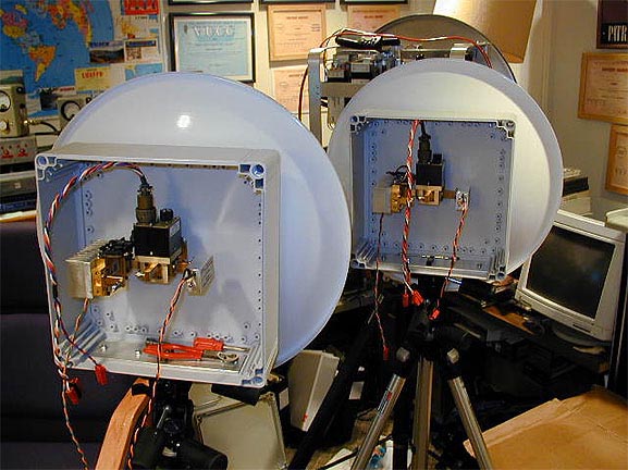
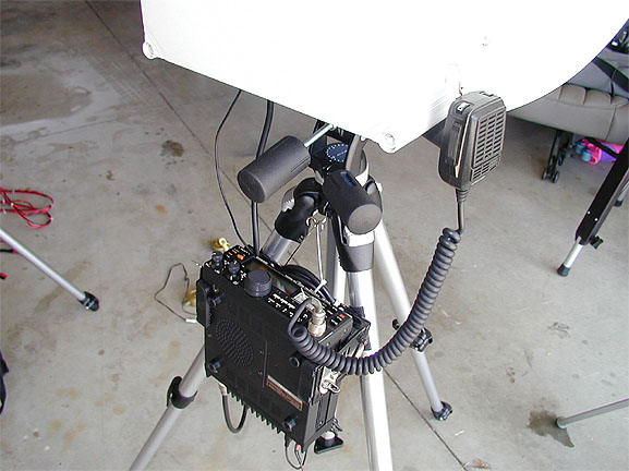
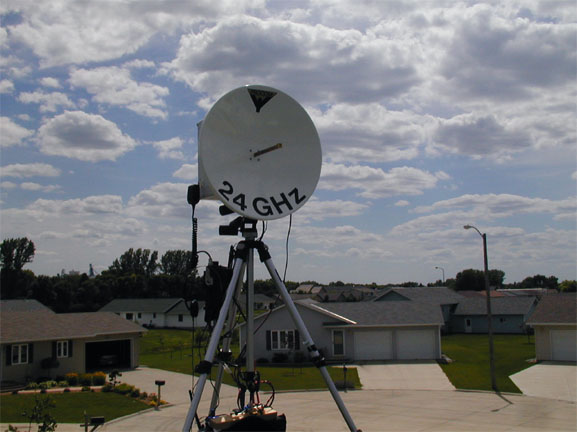
Basic assemblies mounted on dishes and tripods. Tripods are by Bogen with 3030 heads. Dishes and feeds are by Procom. The dish is 48 cm with F/D of 0.4. Gain is approximately 36 dBd. With about 2 watts to the dish, ERP is around 7700 watts!
Procom dish documentation - not real descriptive. Beware, all in mm/cm - think metric!
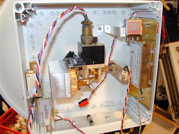
The enclosure is by Hoffman. Thanks Matt - KFØQ for putting me in touch with this particular box!
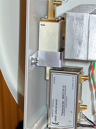
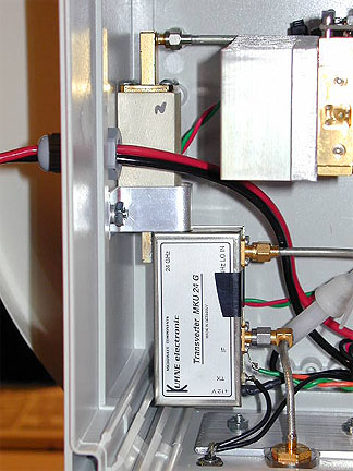
The LO is shown on the right side, soldered to a brass plate. Behind the brass plate is also another large piece of aluminum, which is held tight by bolting thru the Hoffman enclosure.
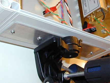
Note aluminum reinforcement plate on the bottom. There are two large metric set screws and a nut/bolt that attaches to the removable plate from the tripod. This then makes it very easy to remove and install the dish on or off the tripod.
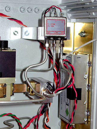
SMA relay mounting detail. Also, showing the detail for mounting the transverter. Just a strap around the image filter. Still gives good access to the internal power pot inside the transverter. All connections are fairly easy to get at.
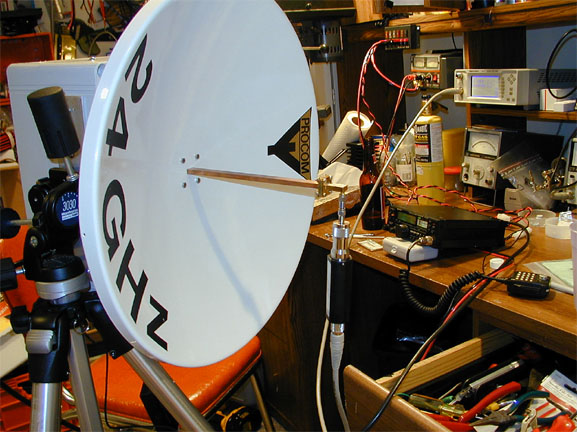
Testing of the power output was possible by soldering a waveguide flange on the end of the Procom waveguide feed. Then a SMA adapter was bolted on. By taking advantage of the Bogen tripod and 3030 head, being able to rotate the dish 90 degrees sideways then allowed the sensor to hang from the adapter with relatively little strain. Note the 10 db attenuator in-between for protecting the head from the 33 dBm power output. The Gigatronics meter gives an ability to program in an offset, so that when you read the screen on the meter, you don't have to do the mental math!
Note that I measured the 10 db attenuator and determined it was about .3 db off. So it really was attenuating 9.7 db. This was an attenuator that was rated to 26.5 GHz. According to specs, it was operating within it's parameters.
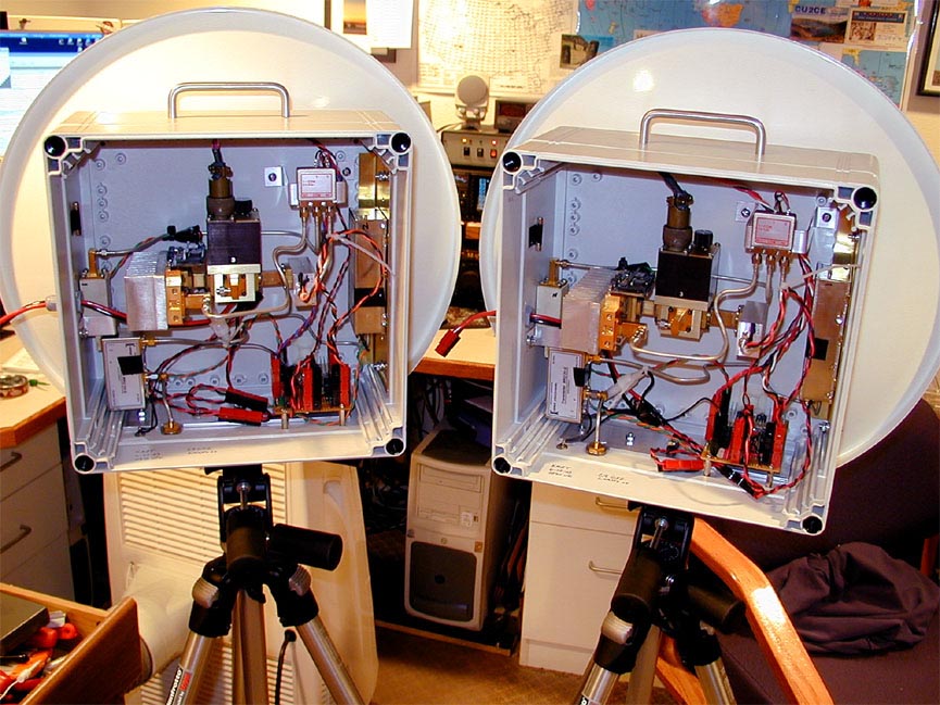
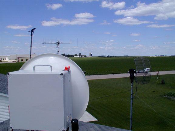
Here are both dishes, all tested and ready for IF radios. Both units tested out fine and gave more than 2 watts output, but were set for 2 watts at 24 GHz. Below are a few more close ups of the construction.
The IF Connection is a panel mount N connector. The PTT from the IF to the transverter and to the control board is an RCA connector. It is located just to the left of the panel mount N connector. All the UT-141 cables were hand made with EF Johnson SMA connectors. Connectors and cable was obtained from Down East Microwave. Thanks Steve!
Note the attenuator on the input of the amplifier. This was to get the trim pot more "in the middle" for power output adjustment to -20dbm to the amp. The transverter was able to be adjusted to a point that would be low enough, but was extremely touchy at the low end of the pot. The attenuator gives one the ability to swing the output a bit more reliably.
Some have said I may need an attenuator on the output of the RX preamp. I decided to give it a try prior to installing one in the RX line.
Here is the IF mounted on the tripod. There is a hook on the tripod that half a "UHF Bowtie" was used to snap too! The IF hangs from this and is kept from sliding from side to side by a few pieces of Velcro. The tripod is able to be disconnected from the dish in a mere moment. The IF takes about 45 seconds to remove also. So all is very handy and easy to assemble and disassemble. The IF rig on the tripod keeps the weight off the dish enclosure as well. (See future update on the New FT-817 IF and mounting)
The Final Test - ON THE AIR! 6-29-03
June 29, 2003 - It was a real nice Sunday afternoon. Gene, NØDQS came to aid in the testing. Our goal was to work 24 GHz in 4 states that afternoon. If that was possible, that would give me 4 more states for the CSVHF "States Above 50 Mhz" for 2002-2003. I knew the competition would be after me, so I really tried hard to get these things done in time for the attempt.
Gene and I both had no idea what to expect. Even if it was going to work at all. Only power output was tested, and that receive noise was still present after cooking with the dish! Also, the RX pre-amp sure made the TR-751 S-meters go up, so that was good! Everything appeared to be in order from what I could tell.
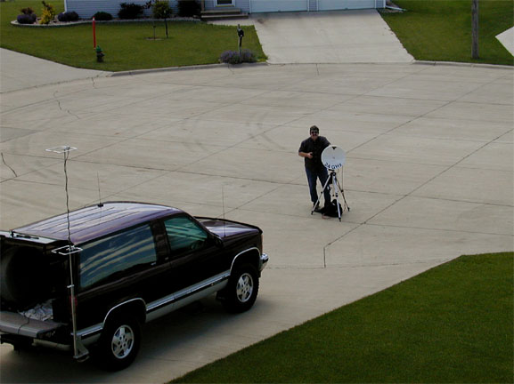
Gene got set up down in the end of the driveway. Going for state #1!
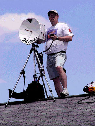
Apparently I was not ready, as I can be seen just messing with the dish!
Things went well. Gene and I found each other right away. Very strong and we could turn the dishes every which way and could hear no problems. Lot of reflections. We were about 5 KHz apart and drifting did not seem to be much of an issue.
Gene then took off for Minnesota, but stopped a few miles away just to do one more test. It took a minute to find him, as we were now 12 KHz apart. Keep in mind Gene was disconnecting power in order to tear down and move. Once we found each other, drifting was not a problem. Signals were extremely strong and the dish could be turned almost 90 degrees and signals could still be heard.
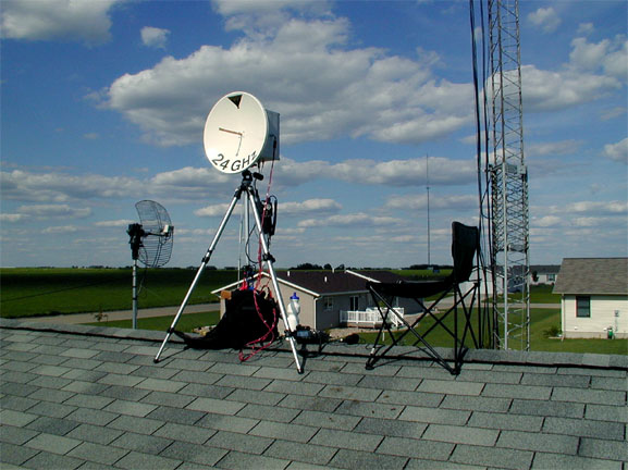
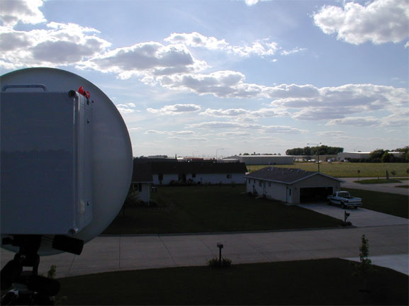
Here is a picture towards this location and the Minnesota location - a slightly NE heading. As you can see I have a great horizon that way. After the quick stop, Gene then headed for Minnesota. His location was such that it was a 30 mile path. When I found him, we were 20 KHz apart. Drifting was not really an issue. Signals were 5x9+20 - rock solid. I moved the dish up/down and sideways anywhere from 5 to 10 degrees and still had good copy. We were simply amazed at how strong the signals were! State #2 in the bag!
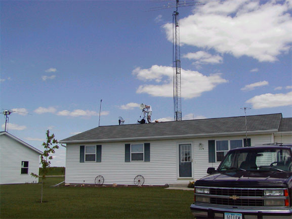
Gene then headed for South Dakota. It took a bit of time so I just sat on the roof and got a nice tan. The WX was pretty good. Not too humid and a bit of breeze. Once in a while the breeze would die down and the clouds would be out of the suns way, that's when it got pretty hot!
I had a coordination radio on the roof, a spare FT-100 and tied that into the main tower's 2 meter antenna. That way Gene and I stayed in close contact.
Here is the path and horizon to South Dakota. A pretty good horizon to the West, a bit obstructed to the NW. The path was only 16 miles and signals were even stronger than before. Found each other right away as I now knew I had to look around a bit! State #3! Piece of cake!
Gene then headed for Nebraska, it was quite a drive to get there but he was up for the challenge. I got a chance to get off the roof for a bit, as now it was becoming more humid and uncomfortable. An hour+ later Gene made it to a spot that he thought looked real good. We calculated it out as a 230 degree beam heading for me. The path was 50 miles. We went back and forth for 10 minutes with nothing heard. We checked and double checked the path heading, I did the best I could with a compass to eyeball the direction the dish was pointed.
We both then broke out the CW keys and took turns sending some Vs, etc as a beacon. After a few minutes Gene indicated that he was hearing me and to keep sending - as he was going to try to peak the signal. After that I peaked up on him and signals were 5x9 on the S-Meter, but with a bit of QSB and noise. We were 27 KHz apart, so that was part of the problem.
The path to Nebraska is shown in this picture. I know that the dish is not pointed that way, but you are essentially looking at the 230 degree path. Some obstructions possibly in town, but hard to tell from this location. Not as good as the other directions.
Gene and I chatted for quite some time on SSB and also tried FM just for grins. When at the peaks of some fading, FM was very nice! After about 5 minutes of chatting, drifting was pretty much non-existent. Interesting on the QSB, it was not evident on the other paths.
Humidity had definitely risen over the time from it took Gene to come from South Dakota to his location in Nebraska. Oh, it was grid # 2 in addition to State #4!
WX was hot, 78 to 90 degrees as the day wore on. Humidity was reported to be 50% for the first half of the day, then it raised about 12%. It is my guess that it was about 65% when Gene made it to Nebraska. Perhaps this explains the slightly reduced signal quality on that particular contact.
Final Comments:
The equipment worked wonderfully, could not have been happier. The audio quality of DB6NT transverters was outstanding. CW and FM all sounding good too.
I want to thank all those again who had a hand in the project. Without your help, suggestions, advice, etc., this would not have turned out so well. Hopefully this article will help others on their way to 24 GHz.
73 and CU on 24 GHz
Now I am off to pour over some topo maps, have to find some good paths to work!
UPDATE: VUCC work finished on 7-12-03. 5 grids. Longest path was to EN14xa - 63 miles. Now to do the paperwork!
UPDATE: VUCC Paperwork applied and signed off on at CSVHF Convention in Tulsa one 7-26-03. Tulsa was a HOOT!
UPDATE: 8-26-03 - First rain scatter contact with NØDQS - 72 miles! - Could be the DX rain scatter record for USA!
UPDATE: VUCC #21 Received 9-10-03
UPDATE: one new grid during the UHF 03 contest - 6 grids total!
UPDATE: two new grids during the September 03 contest - 8 grids total - best DX to date 92 miles!
UPDATE: two new grids 11-2-03 - 10 grids total - best DX to date 114 miles! - New IF Rig - FT-817 - Pictures coming soon!
UPDATE: VUCC 10 Grid Endorsement sticker received, 2-2004. The first endorsement on 24 GHz in the USA! However it
Should be known that W5LUA may have been the first to work 10 grids on the band! (Some via EME)
UPDATE: GRID #11 - December 5th 2004 - EN21LX - 519 RST CW Signals- NØDQS Portable at about 94 miles
UPDATE: GRID #12 - August 27th 2005 - EN11XX - 55 RST SSB Signals- NØDQS Portable at about 78 miles
See the UHF Contest 2005 Writeup for details on the Tower Mounted 24 GHz system.
UPDATE: GRID#13 - December 11th 2005 - EN34fs - 54S RST CW - SNOW SCATTER! - WØZQ Portable at 175 miles
UPDATE: GRID#14 - December 31th 2005 - EN25wb - 56S RST CW - SNOW SCATTER! - WØZQ Portable at 170 miles
UPDATE: GRID#15 - December 31th 2005 - EN35ab - 56S RST CW - SNOW SCATTER! - WØZQ Portable at 176 miles
UPDATE: GRID#16 - January 7th 2006 - EN01wx - 419 RST CW - Tropo! - NØDQS Portable at 125 miles- this is the best Tropo DX yet!
UPDATE: GRID#17 - January 7th 2006 - EN04xa - 419 RST CW - Tropo! - NØDQS Portable at 112 miles
UPDATE: GRID#18 - April 2nd 2006 - EN15wb - 519 RST CW - Rainscatter! - WØZQ Portable at 135 miles
UPDATE: GRID#19 - December 8th 2007 - EN31ax - 599 RST CW! - SNOW SCATTER! NØDQS Portable at 136 miles
UPDATE: GRID#20 - May 2nd 2008 - EN20hx - 519 RST CW! - RAIN SCATTER! NØDQS Portable at 153 miles
Back to the KMØT Homepage.....
Mike - KMØT