External Input Modification for the
DB6NT 12 GHz LO
INTRODUCTION:
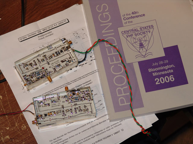
Garry - K3SIW wrote an article for the CSVHF Society 2006 proceedings on how to modify the DB6NT 12 GHz LO for an external frequency source. I read this over after the convention and decided to give it a shot. After I did the mod, it really made sense. However, as I was muddling through it, I learned a few valuable lessons and actually how this thing worked. So, I thought I would post my experiences here along with some photos. Hopefully it will help some of you out. Be sure to check out Garry's article in the proceedings as well!
Why Modify?
First of all, why would you want to do this? Well, these 12 GHz oscillators are typically used as the LO for the 24 GHz DB6NT transverter, which is a 2X multiplier when using a 144 MHz IF radio. I myself starting out on 24 GHz using these to get on the band and came to find that they were usable, but were a bit wanting in terms of consistent frequency accuracy and drift parameters. When we used them, we were never quite sure where each other would be. With Gene - NØDQS or Jon - WØZQ out running around with the portable 24 GHz dishes in varied WX conditions and temperature, it was usually a crapshoot on where one would find one another.
So as I researched methods to make frequency a much more consistent parameter, I discovered that DB6NT made a version of this LO with an external input. This is where one could input an external 125.25 MHz frequency directly to the LO, mimicking the crystal inside the self-contained crystal version. If the external 125.25 MHz frequency source were very accurate and stable, then that would result in a very stable and accurate 24 GHz signal.
Note that the multiplication factor of the 125.25 MHz signal is 96 in order to get to 12024 MHz. Then the transverter multiplies by 2 more to get to 24048 MHz for a total multiplication factor of 192. Add 144 MHz to 24048 MHz and you get 24.192.000 GHz. So one can see that just a very slight variation in the input frequency to the LO at 125.25 MHz can make one many KHz off frequency at 24 GHz!
In 2005, I reworked my portable 24 GHz dishes with the DB6NT 12 GHz LOs that had the Option-01, which was no internal crystal. I looked briefly at modifying the 12 GHz LOs at that time, but I could not figure it out as I ran out of time getting ready for the UHF 2005 Contest. So, I had 3 extra 12 GHz LOs with internal crystals. I sold two and kept one as a spare. Now here in 2006, I began gathering parts for another 24 GHz system (Gridinator II) and began looking into the 12 GHz LO issue, since I wanted to use an external 125.25 MHz source to drive the system.
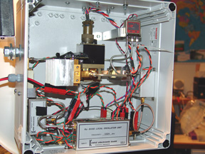
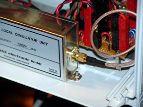
Here you see one of the portable 24 GHz dishes, reworked in 2005.
(Note the Option-01 12 GHz oscillator and 125.25 MHz OCXO)
But what do you do if you just have the crystal version and don't want to buy the Option-01 version? Well, here is how I managed the modification....
Nuts and Bolts...
The internal 125.25 MHz crystal circuit is powered by the step-down voltage regulator 78L05, which is near where it shows an external oscillator input on the schematic. Garry - K3SIW had shown in his write-up that he cut the output of the regulator circuit, but put in a few bypass capacitors to the outside of the tin box if you wanted to use the crystal again. Basically all you would do is jumper the two bypass capacitors outside of the tin box in order to activate the crystal circuit again. The voltage bypass is a great idea if you have bypass caps laying around. I however did not, so all I had to do was make a simple cut of the 5V trace that went to the circuitry after the 78L05. Garry then indicated to put a resistor on the output of the regulator to ground so the regulator always had a load. I personally would have never thought of this, but it sure seemed like a good idea, so that is what I did as well.
The next step was to get an external oscillator signal into the box. This meant drilling a hole and getting some type of cable near the "EXT OSZ IN" shown on the schematic. Garry indicated that this is a very delicate process, so much care needed to be taken here. I found some SMA Female connectors for 085 semi-rigid hardline in the junk box that looked like they would solder to the side of the box, so that was a nice find.
I choose my spot to drill the hole and got my hand drill out. As I was drilling, the kids waltzed into the shack and started screwing around. In fact one happened to bump into me just as the bit went through the tin box. The drill bit went in too fast and appeared to bump something on the inside. After the steam boiled off, I began to inspect the inside circuit board but did not see anything wrong, so I proceeded with the 085 cable install.
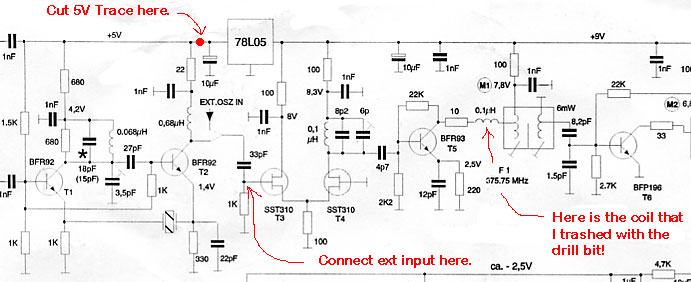
Garry indicated that one needs to bring the signal in - terminated with another capacitor near the "EXT OSZ IN". The connection is actually made at the junction of the 1K, T3 and 33 pf capacitor. Garry said the value of the capacitor is not really critical and used a 27 pf value, but one needs to keep the physical size of the 0805 package. Well, I did not have any surface capacitors laying around, so I used a ceramic disc capacitor. The one I chose was the same as I used to feed my 5.7 and 10 GHz transverters when I modified them last year for external input. (See the Rover Mania II Contest writeup for details) Anyway, I figured if it was good enough for the transverter input, it would work for this too.
Picture of the DB6NT 10 GHz transverter modification for external LO input I did in 2005.
(The ceramic disc capacitor from DB6NT for this mod was the same I tried in the 12 GHz LO modification)
(It's the green one with the black top...)
Well, the modification and installation of the external input was pretty easy, but when powered up, it did not work. I had tested the LO during various steps while doing the mod, just to make sure I had not broken anything, but did not retest after I drilled the hole in the box. Well, I started to snoop around and began to suspect a surface inductor that was in-line with where I drilled the hole. (The inductor was the 0.1uH that feeds into the first set of tuning slugs - F1 - for 375.75 MHz) I got my VOM out and it seemed that there was no continuity across it. I got out my magnifying glass and began to inspect the wires wound around the form; sure enough they were cut in a few spots. Apparently the tip of the drill bit had made its mark! (Garry was right - be CAREFUL!) Well I let out a few four letter words and began to wonder where I was going to get a surface wound inductor like this on a Sunday night in Sioux Center Iowa. Not a real good chance the local farming implement dealers would have such an animal...
As I was sorting thru the various junk boxes, I came across some small magnet wire coils I had practice wound when I was building a DEMI 902 MHz transverter. I wondered if I just put one of those in if I could get the LO to run at least. I figured some inductance was better than none. As I was thinking of simply jumpering across the spot. So, the next hour was spent carefully removing the surface inductor and forming up the magnet wire coil. Soldering this in was a bit tricky as it was not a good fit, and I was trying not to wreck the rest of the surrounding surface components while doing so.
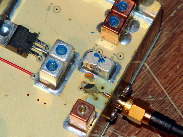
One can see the red magnet wire coil I wound to replace the surface inductor I trashed.
(Left side of the picture near the corner of the cable coming in)
Note the 1K from loading resistor connected to the tin box and output pad of the regulator.
At this point, I powered on the 12 GHz LO and input the 125.25 MHz signal. I was getting 12024 MHz out! However the power was down quite a bit. Spec for this was about 40mw, I was getting less than 5mw.
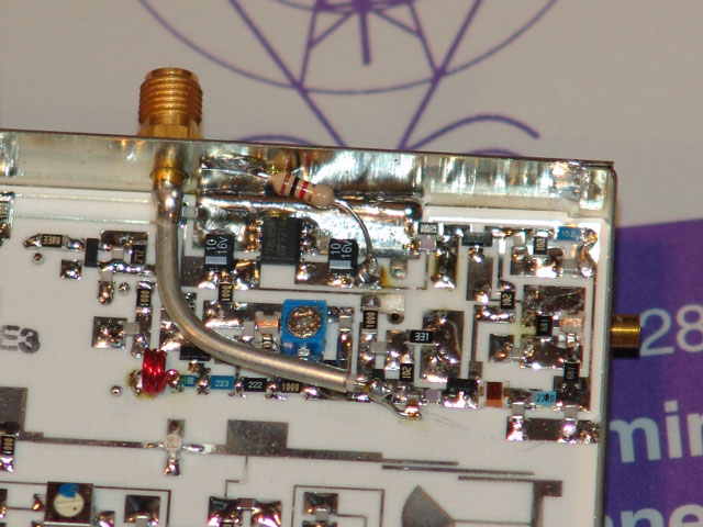
See the connection of the external input, here it shows a 0805 size surface capacitor...
(The ceramic disc capacitor I used did not work well....more on this later)
Note the 5V trace cut from the regulator output pad - near the bottom of the 1K resistor.
Some relief was felt as the tension melted away, I had somewhat fixed what I broke. I was then off to figure out why the power output was low. I tuned the F1 slugs a bit and managed to get a few more dBm, but that was not enough. The only other thing I could think of was that the coil I put in was just not going to let it work any better, or the ceramic disc input capacitor I was using was not going to work out. (Sorry no picture of this...)
Finishing up...
Well, it was a good thing I was working on my own DB6NT LO for this practice run, because I was also supposed to modify NØKP's 12 GHz LO to help him get on 24 GHz. As he had an OCXO that was going to be used to drive it and just had the crystal version of the 12 GHz LO. So I called him up and told him all the things I was going through, but he said to "go for it" anyway. Also, he had some 0805 size surface capacitors that I could use for the input. I figured with the lessons learned, I had a much better chance of coming thru this.
I first measured the LO's output before proceeding with any construction, it was about 70mw! Much more than I expected. I called Dave back and he confirmed that his data sheet said the same thing. Odd I though since I had quite of few of the DB6NT LOs and they were all in the 35 to 45mw range.
Anyway, this time I got out the drill press and made my hole in the side of the tin box. This made short work of that and it was safe. (Too lazy with my own stuff I guess to get the drill press out :)
Dave supplied the 0805 surface capacitors. All he had was 100 pf, but it was worth a try. I got the cable and capacitor connected nicely to the junction at T3, cut the 5V trace and installed the load resistor.
I checked everything over real good (no wrecked inductor this time!) and put power to it along with 1 mw of external 125.25 MHz input. Power measured at 70mw again! It worked perfectly!
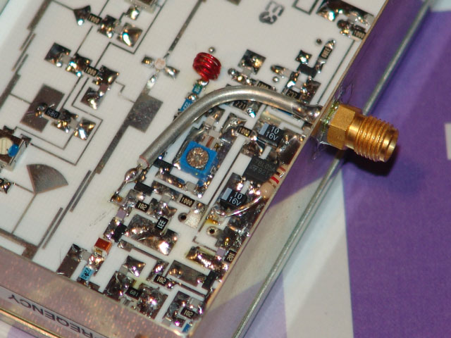
Here is the mod to Dave's - NØKP's 12 GHz LO
(Note the surface inductor at the corner of the input cable, that's the one I wrecked on my unit)
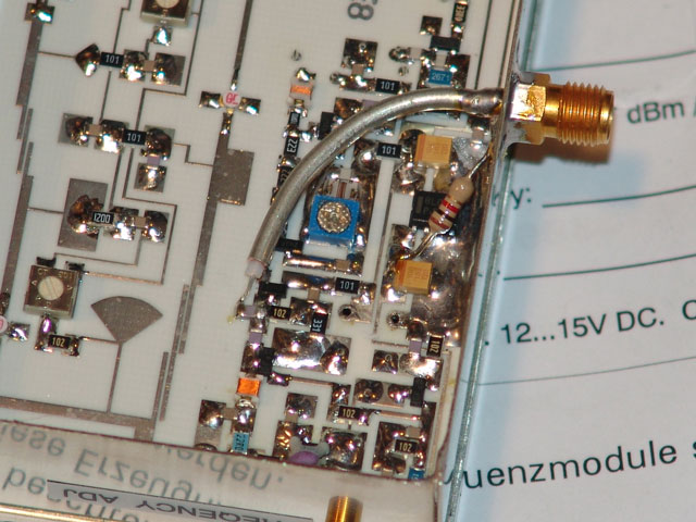
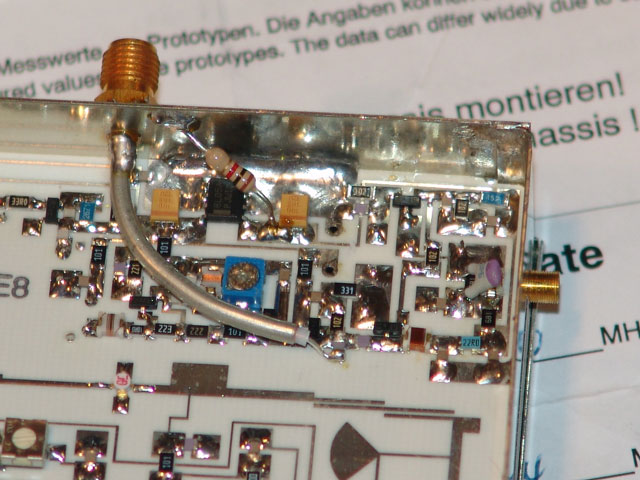
Here again on Dave's LO, you can see the connection at the T3 junction with the surface capacitor.
(Note the 5V trace cut and loading resistor)
I gave Dave the good news and then proceeded to switch out the ceramic disc capacitor for a surface capacitor on my 12 GHz LO. When I did this, the power went up quite a bit to about 20mw, 1/2 of spec. So, the only thing I have left to do on my unit is to replace the 0.1uH surface inductor. Anybody out there have a spare or know where to get them? If so please let me know!
Again, if one wants to activate the crystal once more, just jumper back in the cut 5V trace and take off the external 125.25 MHz input, then your good to go! Garry indicated that one might need to adjust the capacitor "Frequency Adjust" trimmer on the tin box exterior due to loading on the circuit from the external input. This however did not appear to be necessary in my case.
Good luck with your 12 GHz LO modifications. Again, thanks to Garry for his article in the 2006 CSVHF Society Proceedings, without this I would have probably never tried to attempt the modification.
73 de KMØT